ā Evacuated Solar Energy Collector Technical Reference
ā Evacuated Solar Energy Collector Technical Reference
ā Evacuated Solar Energy Collector Technical Reference

Create successful ePaper yourself
Turn your PDF publications into a flip-book with our unique Google optimized e-Paper software.
(5.0) How to design a THERMOMAX � system<br />
The first step to ensure enjoyment of<br />
� �<br />
your THERMOMAX MEMOTRON <strong>Evacuated</strong><br />
Heat-Pipe System over a long period<br />
of time is to design and specify the collector<br />
size and the associated components<br />
correctly.<br />
The following explanations are for installations<br />
up to 9 m² (90 tubes) of collector<br />
area. Some typical examples for the<br />
various components are given at the end<br />
of this chapter.<br />
(5.1) <strong>Collector</strong> Area<br />
If you are using the installation to provide<br />
hot water only it is strongly recommended<br />
to aim for 100% solar coverage<br />
during the summer months only. If the<br />
system has to provide additional energy<br />
for heating sy stems in the winter time or<br />
other applications an option for re-routing<br />
the excess heat has to be installed (i.e.<br />
heat-sink, connecting to a swimming pool)<br />
to avoid long stagnation times in the summer.<br />
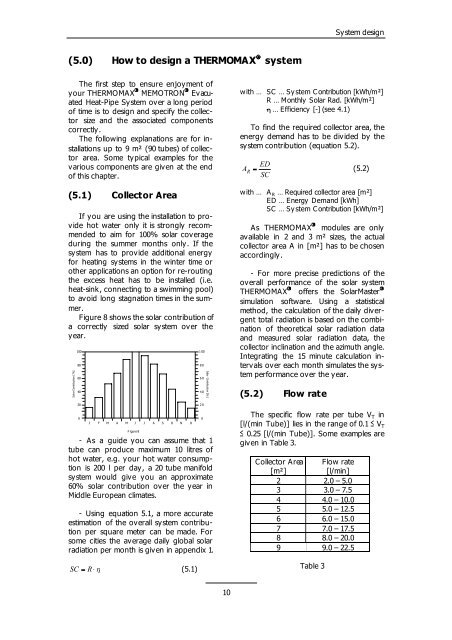
Figure 8 shows the solar contribution of<br />
a correctly sized solar system over the<br />
year.<br />
<strong>Solar</strong> Contribution [ %]<br />
100<br />
80<br />
60<br />
40<br />
20<br />
0<br />
J<br />
F M A M J J A S O N D<br />
Figure 8<br />
- As a guide you can assume that 1<br />
tube can produce maximum 10 litres of<br />
hot water, e.g. your hot water consumption<br />
is 200 l per day, a 20 tube manifold<br />
system would give you an approximate<br />
60% solar contribution over the year in<br />
Middle European climates.<br />
- Using equation 5.1, a more accurate<br />
estimation of the overall system contribution<br />
per square meter can be made. For<br />
some cities the average daily global solar<br />
radiation per month is given in appendix 1.<br />
SC � R ��<br />
(5.1)<br />
100<br />
80<br />
60<br />
40<br />
20<br />
0<br />
<strong>Solar</strong> Contribution [% ]<br />
10<br />
<strong>Collector</strong> Area Flow rate<br />
[m²]<br />
[l/min]<br />
2 2.0 – 5.0<br />
3 3.0 – 7.5<br />
4 4.0 – 10.0<br />
5 5.0 – 12.5<br />
6 6.0 – 15.0<br />
7 7.0 – 17.5<br />
8 8.0 – 20.0<br />
9 9.0 – 22.5<br />
Table 3<br />
Sy stem design<br />
with … SC … System Contribution [kWh/m²]<br />
R … Monthly <strong>Solar</strong> Rad. [kWh/m²]<br />
� … Efficiency [-] (see 4.1)<br />
To find the required collector area, the<br />
energy demand has to be divided by the<br />
sy stem contribution (equation 5.2).<br />
ED<br />
AR �<br />
SC<br />
(5.2)<br />
with … A R … Required collector area [m²]<br />
ED … <strong>Energy</strong> Demand [kWh]<br />
SC … System Contribution [kWh/m²]<br />
As THERMOMAX � modules are only<br />
available in 2 and 3 m² sizes, the actual<br />
collector area A in [m²] has to be chosen<br />
accordingly.<br />
- For more precise predictions of the<br />
overall performance of the solar system<br />
� �<br />
THERMOMAX offers the <strong>Solar</strong>Master<br />
simulation software. Using a statistical<br />
method, the calculation of the daily divergent<br />
total radiation is based on the combination<br />
of theoretical solar radiation data<br />
and measured solar radiation data, the<br />
collector inclination and the azimuth angle.<br />
Integrating the 15 minute calculation interv<br />
als over each month simulates the sy stem<br />
performance over the year.<br />
(5.2) Flow rate<br />
The specific flow rate per tube V T in<br />
[l/(min Tube)] lies in the range of 0.1 � V T<br />
� 0.25 [l/(min Tube)]. Some examples are<br />
given in Table 3.