ā Evacuated Solar Energy Collector Technical Reference
ā Evacuated Solar Energy Collector Technical Reference
ā Evacuated Solar Energy Collector Technical Reference

You also want an ePaper? Increase the reach of your titles
YUMPU automatically turns print PDFs into web optimized ePapers that Google loves.
�<br />
(6.0) How to install a THERMOMAX System<br />
This chapter explains the installation<br />
procedures for the THERMOMAX � <strong>Evacuated</strong><br />
<strong>Solar</strong> <strong>Collector</strong> System with the various<br />
roof fixing kits.<br />
(6.1) General<br />
Due to the overall weight of the unit it<br />
MUST BE MOUNTED SECURELY TO A<br />
STRONG SECTION OF THE ROOF.<br />
Please observe the following simple<br />
precautions to ensure maximum efficiency<br />
from your THERMOMAX <strong>Solar</strong> <strong>Energy</strong><br />
<strong>Collector</strong> assembly.<br />
Locate the solar collector sy stem so<br />
that the tubes receive maximum sunshine<br />
through the day with no or minimum<br />
shading. NOTE: The coated surface of the<br />
absorber must face uppermost (±30°) and<br />
as south facing as possible (Azimuth angle).<br />
The solar collector sy stem can, be<br />
mounted at any suitable angle between<br />
25° and almost vertical position (Inclination<br />
Angle). The recommended angle is<br />
the same as the geographical latitude of<br />
the collector location.<br />
In areas where local water is known to<br />
be hard or aggressive, a heat exchanger<br />
must be used and the use of a water softener<br />
is recommended, otherwise regular<br />
cleaning of the system will be required.<br />
In areas where the chloride ion<br />
concentration is greater than 40 ppm a<br />
heat exchanger must be used in the hot<br />
water storage tank . The solar sy stem<br />
should be filled with distilled or<br />
dechlorinated water. Check with your local<br />
w ater authorities.<br />
CA UTIONA RY NOTES:<br />
- Mak e sure sufficient space is left between<br />
the manifold and roof apex for<br />
ease of working on pipework within<br />
the loft span.<br />
- Wear gloves and safety goggles when<br />
working with glass tubes.<br />
- Do not use sharp objects to open the<br />
covers or the box as this may scratch<br />
or damage the glass tube.<br />
- Do not remove the tubes from packaging<br />
until ready to assemble.<br />
�<br />
19<br />
Installation details<br />
- Connect the manifold, all the pipework<br />
and the pump first before installing<br />
the tubes.<br />
Pipes running horizontally should always<br />
be installed rising slightly to avoid the<br />
creation of air pockets.<br />
Note that when installing the<br />
collector and pipe work it is<br />
important that all local authority<br />
regulations, relevant technical and<br />
safety standards are adhered to.<br />
(6.2) Manifold Connections<br />
Series Connections<br />
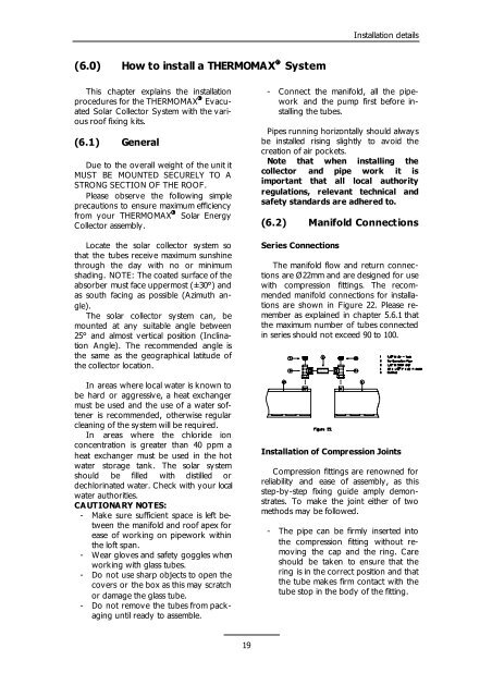
The manifold flow and return connections<br />
are Ø22mm and are designed for use<br />
with compression fittings. The recommended<br />
manifold connections for installations<br />
are shown in Figure 22. Please remember<br />
as explained in chapter 5.6.1 that<br />
the maximum number of tubes connected<br />
in series should not exceed 90 to 100.<br />
Installation of Compression Joints<br />
Compression fittings are renowned for<br />
reliability and ease of assembly, as this<br />
step-by-step fixing guide amply demonstrates.<br />
To make the joint either of two<br />
methods may be followed.<br />
- The pipe can be firmly inserted into<br />
the compression fitting without removing<br />
the cap and the ring. Care<br />
should be taken to ensure that the<br />
ring is in the correct position and that<br />
the tube makes firm contact with the<br />
tube stop in the body of the fitting.