ā Evacuated Solar Energy Collector Technical Reference
ā Evacuated Solar Energy Collector Technical Reference
ā Evacuated Solar Energy Collector Technical Reference

You also want an ePaper? Increase the reach of your titles
YUMPU automatically turns print PDFs into web optimized ePapers that Google loves.
PCU 20-<br />
60<br />
Sys.<br />
Kit<br />
PCU 90-<br />
240<br />
C ollector<br />
Area [m²]<br />
Number<br />
of Tubes<br />
2 - 4 20 – 40<br />
5 - 6 50 – 60<br />
7 - 9<br />
Table 5<br />
70 – 90<br />
(240)<br />
As the flow rate V S is already determined<br />
(see chapter 5.2) the pressure drop<br />
�p s in [Pa] of the sy stem has to be calculated.<br />
The sy stem pressure drop �p s<br />
equals the sum of all single pressure drops<br />
of components in the installation connected<br />
in series (not parallel). Mainly<br />
these are - <strong>Solar</strong> <strong>Collector</strong>,<br />
- Pipe Work and<br />
- Heat Exchanger.<br />
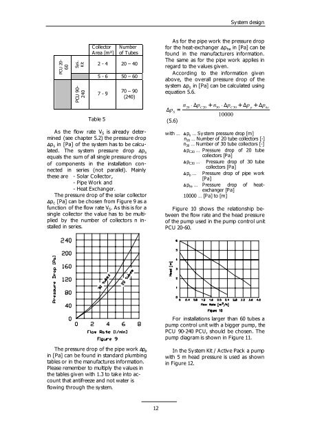
The pressure drop of the solar collector<br />
�pc [Pa] can be chosen from Figure 9 as a<br />
function of the flow rate V S.<br />
As this is for a<br />
single collector the value has to be multiplied<br />
by the number of collectors n installed<br />
in series.<br />
The pressure drop of the pipe work��p p<br />
in [Pa] can be found in standard plumbing<br />
tables or in the manufactures information.<br />
Please remember to multiply the values in<br />
the tables given with 1.3 to take into account<br />
that antifreeze and not water is<br />
flowing through the system.<br />
12<br />
Sy stem design<br />
As for the pipe work the pressure drop<br />
for the heat-exchanger �p he in [Pa] can be<br />
found in the manufacturers information.<br />
The same as for the pipe work applies in<br />
regard to the values given.<br />
According to the information given<br />
above, the overall pressure drop of the<br />
sy stem �ps in [Pa] can be calculated using<br />
equation 5.6.<br />
�p<br />
S<br />
(5.6)<br />
�<br />
n<br />
� �p<br />
� n<br />
� �p<br />
20 C20<br />
30 C30<br />
p he<br />
10000<br />
� �p<br />
� �p<br />
with … �p s … Sy stem pressure drop [m]<br />
n20 … Number of 20 tube collectors [-]<br />
n30 … Number of 30 tube collectors [-]<br />
�pC20 … Pressure drop of 20 tube<br />
collectors [Pa]<br />
�pC30 … Pressure drop of 30 tube<br />
collectors [Pa]<br />
�p p … Pressure drop of pipe work<br />
[Pa]<br />
�phe … Pressure drop of heatexchanger<br />
[Pa]<br />
10000 … [Pa] to [m]<br />
Figure 10 shows the relationship between<br />
the flow rate and the head pressure<br />
of the pump used in the pump control unit<br />
PCU 20-60.<br />
For installations larger than 60 tubes a<br />
pump control unit with a bigger pump, the<br />
PCU 90-240 PCU, should be chosen. The<br />
pump diagram is shown in Figure 11.<br />
In the System Kit / Active Pack a pump<br />
with 5 m head pressure is used as shown<br />
in Figure 12.