ā Evacuated Solar Energy Collector Technical Reference
ā Evacuated Solar Energy Collector Technical Reference
ā Evacuated Solar Energy Collector Technical Reference

You also want an ePaper? Increase the reach of your titles
YUMPU automatically turns print PDFs into web optimized ePapers that Google loves.
<strong>Technical</strong> product description<br />
nal source, uses this heat to evaporate the liquid (latent heat) and then releases the latent<br />
heat by reverse transformation (condensation) at a heat sink region. This process is repeated<br />
continuously as the condensed fluid returns to its original position due to gravity.<br />
Rapid temperature swings produce localised stresses within all glass to metal joints limiting<br />
the life of the joint. In order to remove these stresses a specially designed THERMAL SHOCK<br />
ABSORBER is incorporated into the THERMOMAX � �<br />
Memotron <strong>Evacuated</strong> <strong>Solar</strong> <strong>Collector</strong><br />
Tube. This patented thermal shock absorber is made of a metal having high thermal resistance<br />
and high mechanical strength to completely absorb the temperature swing.<br />
(3.1.2) The <strong>Evacuated</strong> Glass Tube<br />
�<br />
In a THERMOMAX collector the absorber plate and its heat-pipe is hermetically sealed within<br />
an evacuated glass tube. This protects the high efficiency of the absorber plate from adverse<br />
weathering influences as well as airborne pollutants.<br />
The vacuum in the evacuated glass tube is 10 -5 mbar. This can only be reached and maintained<br />
over a long period of time through a specialised evacuation process in production resulting<br />
in an almost total elimination of convection and conduction losses from the collector.<br />
Due to the tubular shape each glass tube offers<br />
minimal resistance to wind and snow build up.<br />
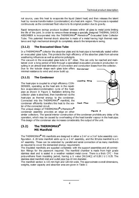
(3.1.3) The Condenser<br />
The heat-pipe is coupled to a high efficiency CON-<br />
DENSER, operating as the heat sink in the repetitive<br />
evaporation/condensation cycle of the heatpipe<br />
as shown in Figure 3. Radiation striking the<br />
collector plate is absorbed, then transferred via the<br />
heat-pipe as thermal energy to the condenser.<br />
Connected into the THERMOMAX � manifold, the<br />
condenser efficiently transfers this heat to the wa-<br />
ter of the connected circuit.<br />
The unique design of THERMOMAX � ’s Memotron<br />
condenser assembly provides an edge on other<br />
similar collectors. The special interior construction of the condenser prohibits any delay of its<br />
operation, which may be caused by overheating of the heat transfer vapour in the heat-pipe.<br />
This design of the condenser also increases considerably the output of the unit.<br />
(3.2) The THERMOMAX �<br />
MS Manifold<br />
The THERMOMAX � MS manifolds are designed in either a 2 m² or a 3 m² tube assembly configuration.<br />
A 20 tube manifold adds up to a 2 m² assembly, and the 30 tube manifold to a 3<br />
m² assembly. These can be extended by parallel and serial connection of as many manifolds<br />
as required to cover the demanded energy requirement.<br />
The insulated manifolds are supplied completely with the support assemblies and all connection<br />
fittings for the pipework required. The manifold chamber is made from high grade<br />
stainless steel and is sealed in a weather resistant metal cover. There is a thick CFC - free<br />
polyurethane foam insulating jacket, having a U value [W/(mK)] of 0.28 � U � 0.35. The<br />
stainless steel manifold inlet and outlet pipe has 22 mm diameter.<br />
The manifold section is 115 mm high and 120 mm wide. The approximate overall dimensions,<br />
weights, water capacity and absorber area are given in Table 1:<br />
4<br />
�