ā Evacuated Solar Energy Collector Technical Reference
ā Evacuated Solar Energy Collector Technical Reference
ā Evacuated Solar Energy Collector Technical Reference

Create successful ePaper yourself
Turn your PDF publications into a flip-book with our unique Google optimized e-Paper software.
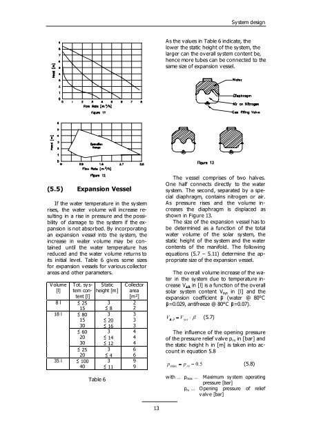
(5.5) Expansion Vessel<br />
If the water temperature in the system<br />
rises, the water volume will increase resulting<br />
in a rise in pressure and the possibility<br />
of damage to the system if the expansion<br />
is not absorbed. By incorporating<br />
an expansion vessel into the system, the<br />
increase in water volume may be contained<br />
until the water temperature has<br />
reduced and the water volume returns to<br />
its initial level. Table 6 gives some sizes<br />
for expansion vessels for various collector<br />
areas and other parameters.<br />
Volume<br />
[l]<br />
8 l<br />
Tot. sy stemcontent<br />
[l]<br />
� 25<br />
15<br />
18 l � 80<br />
15<br />
30<br />
� 60<br />
20<br />
30<br />
� 25<br />
20<br />
35 l � 100<br />
40<br />
Static<br />
height [m]<br />
Table 6<br />
3<br />
� 8<br />
3<br />
� 20<br />
� 16<br />
3<br />
� 14<br />
� 12<br />
3<br />
� 4<br />
3<br />
� 11<br />
C ollector<br />
area<br />
[m²]<br />
2<br />
2<br />
3<br />
3<br />
3<br />
4<br />
4<br />
4<br />
6<br />
6<br />
9<br />
9<br />
13<br />
Sy stem design<br />
As the values in Table 6 indicate, the<br />
lower the static height of the system, the<br />
larger can the overall system content be,<br />
hence more tubes can be connected to the<br />
same size of expansion vessel.<br />
The vessel comprises of two halv es.<br />
One half connects directly to the water<br />
sy stem. The second, separated by a special<br />
diaphragm, contains nitrogen or air.<br />
As pressure rises and the v olume increases<br />
the diaphragm is displaced as<br />
shown in Figure 13.<br />
The size of the expansion vessel has to<br />
be determined as a function of the total<br />
water v olume of the solar sy stem, the<br />
static height of the sy stem and the water<br />
contents of the manifold. The following<br />
equations (5.7 – 5.11) determine the appropriate<br />
size of the expansion vessel.<br />
The overall volume increase of the water<br />
in the system due to temperature increase<br />
V �� in [l] is a function of the overall<br />
solar sy stem content V sys in [l] and the<br />
expansion coefficient � (water @ 80°C<br />
�=0.029, antifreeze @ 80°C �=0.07).<br />
V<br />
� V<br />
� � sys<br />
� �<br />
(5.7)<br />
The influence of the opening pressure<br />
of the pressure relief valve p rv in [bar] and<br />
the static height h in [m] is taken into account<br />
in equation 5.8<br />
p<br />
max<br />
� p rv<br />
�<br />
0.<br />
5<br />
(5.8)<br />
with … pmax … Maximum sy stem operating<br />
pressure [bar]<br />
prv … O pening pressure of relief<br />
valve [bar]