ā Evacuated Solar Energy Collector Technical Reference
ā Evacuated Solar Energy Collector Technical Reference
ā Evacuated Solar Energy Collector Technical Reference

You also want an ePaper? Increase the reach of your titles
YUMPU automatically turns print PDFs into web optimized ePapers that Google loves.
p d h<br />
� p � 0 . 1�<br />
h<br />
(5.9)<br />
with … p … set pressure for diaphragm [bar]<br />
d<br />
p h … Pressure in highest point of sy stem<br />
(e.g. 0.5 bar) [bar]<br />
0.1 … [m] to [bar]<br />
h … static height [m]<br />
To ensure a sufficient v olume of water<br />
in the system at all times a minimum volume<br />
V c in [l] must be present in the expansion<br />
vessel in the cold condition. With<br />
V c and the values calculated before the<br />
nominal size of the expansion vessel V in<br />
[l] can be calculated with equations 5.10<br />
and 5.11.<br />
Vc � V sys � 0. 015 �1[<br />
l]<br />
(5.10)<br />
with … V c … Water v olume in expansion v essel<br />
in cold sy stem condition [l]<br />
(minimum 1 litre)<br />
V sys … O v erall solar sy stem content [l]<br />
V<br />
n<br />
�<br />
�V � V � n � V �� �p � 1�<br />
c<br />
� �<br />
p<br />
col<br />
max<br />
col<br />
� p<br />
d<br />
max<br />
n<br />
(5.11)<br />
with … Vn … Nominal v olume of expansion<br />
v essel [l]<br />
V c … Water v olume in expansion v essel<br />
in cold sy stem condition [l]<br />
V�� … V olume increase due to temp.<br />
increase [l]<br />
n … Number of manifolds installed<br />
col<br />
[-]<br />
V col … Water v olume of single manifold<br />
[l]<br />
p max … Maximum sy stem operating<br />
pressure [bar]<br />
p … Set pressure for diaphragm [bar]<br />
d<br />
Having calculated the nominal size of<br />
the expansion vessel V n the closest available<br />
vessel size will be chosen.<br />
(5.6) Hydraulics<br />
(5.6.1) <strong>Collector</strong> System<br />
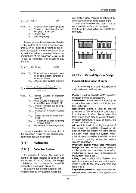
As mentioned before the maximum<br />
number of tubes installed in series should<br />
not exceed 90 to 100 tubes. For bigger<br />
installations the recommended manifold<br />
connection is shown in Figure 14.<br />
To achieve the highest output of the<br />
whole system every manifold needs the<br />
14<br />
Sy stem design<br />
correct flow rate. This can be achieved by<br />
connecting the manifolds according to<br />
“Tichelmann” (the flow and return pipe of<br />
each manifold adds up to the same<br />
length) or by using valves to regulate the<br />
flow rate.<br />
(5.6.2) Overall System Design<br />
Functional description of parts<br />
The following is a brief description of<br />
main parts used in the sy stem.<br />
Pump is used to circulate water from the<br />
collector to the user application.<br />
Flow-meter is attached to the pump to<br />
monitor flow rate of water within the system<br />
(optional).<br />
Non-Return Valve is used to prevent<br />
gravitational flow of water in solar circuit<br />
from the tank to the collector when the<br />
tank temperature may be greater than the<br />
collector temperature (e.g. at night). Be<br />
sure to install correctly.<br />
Air vent is fitted at the highest point of<br />
the system to facilitate removal of air<br />
pock ets from the sy stem. Air v ents should<br />
be open when filling the system. Automatic<br />
airvents should be fitted with a valve<br />
to prevent opening when the system<br />
reaches stagnation.<br />
Pressure Relief Valve and Pressure<br />
Gauge are used to monitor the pressure<br />
of the sy stem and to serv e as a safety<br />
mechanism to avoid over pressurising of<br />
the sy stem (max. 5 bar).<br />
Filling Loop consists of a flexible hose<br />
and stop valve and connects the water<br />
mains supply to the hose connector and<br />
filling valve.<br />
Expansion Vessel is used to contain increased<br />
water volume in the system due