


Create successful ePaper yourself
Turn your PDF publications into a flip-book with our unique Google optimized e-Paper software.
Removing the System Memory (RAM)<br />
The computer has two memory sockets for 200 pin Small Outline Dual In-line Memory Modules (SO-DIMM) supporting<br />
DDRIII (DDR3) Up to 1066 MHz. The main memory can be expanded up to 4GB. The SO-DIMM modules supported<br />
are 1024MB and 2048MB DDRIII Modules. The total memory size is <strong>au</strong>tomatically detected by the POST routine once<br />
you turn on your computer.<br />
Memory Upgrade Process<br />
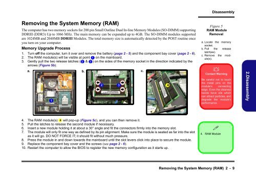
1. Turn off the computer, turn it over and remove the battery (page 2 - 5) and the component bay cover (page 2 - 6).<br />
2. The RAM module(s) will be visible at point 1 on the mainboard.<br />
3. Gently pull the two release latches ( 2<br />
arrows (Figure 5b).<br />
& 3 ) on the s<strong>id</strong>es of the memory socket in the direction indicated by the<br />
a. b. c.<br />
1<br />
2 3<br />
4<br />
4. The RAM module(s) 4<br />
will pop-up (Figure 5c), and you can then remove it.<br />
5. Pull the latches to release the second module if necessary.<br />
6. Insert a new module holding it at about a 30° angle and fit the connectors firmly into the memory slot.<br />
7. The module will only fit one way as defined by its pin alignment. Make sure the module is seated as far into the slot<br />
as it will go. DO NOT FORCE IT; it should fit without much pressure.<br />
8. Press the module in and down towards the mainboard until the slot levers click into place to secure the module.<br />
9. Replace the component bay cover and the screws (see page 2 - 6).<br />
10. Restart the computer to allow the BIOS to register the new memory configuration as it starts up.<br />
Disassembly<br />
Figure 5<br />
RAM Module<br />
Removal<br />
a. Locate the memory<br />
socket.<br />
b. Pull the release<br />
latch(es).<br />
c. Remove the module(s).<br />
�<br />
Contact Warning<br />
Be careful not to touch<br />
the metal pins on the<br />
module’s connecting<br />
edge. Even the cleanest<br />
hands have oils which<br />
can attract particles, and<br />
degrade the module’s<br />
performance.<br />
�<br />
4. RAM Module<br />
Removing the System Memory (RAM) 2 - 9<br />
2.Disassembly


