

DATA SHEET - IEETA
DATA SHEET - IEETA
DATA SHEET - IEETA

Create successful ePaper yourself
Turn your PDF publications into a flip-book with our unique Google optimized e-Paper software.
Philips Semiconductors Product specification<br />
8-bit microcontroller with on-chip CAN P8xC592<br />
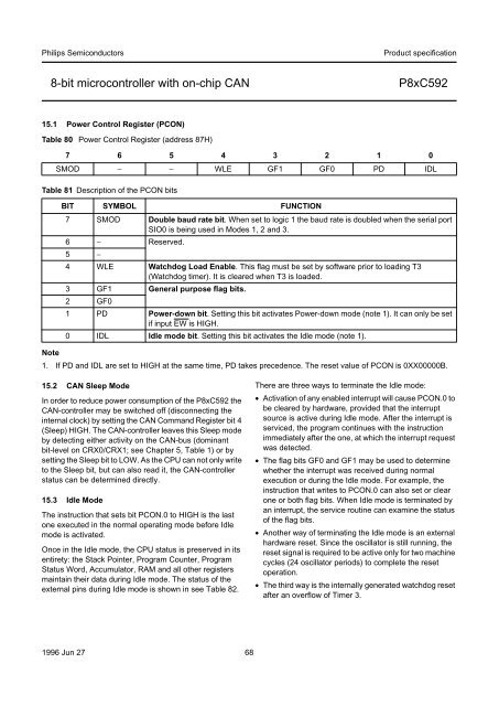
15.1 Power Control Register (PCON)<br />
Table 80 Power Control Register (address 87H)<br />
7 6 5 4 3 2 1 0<br />
SMOD − − WLE GF1 GF0 PD IDL<br />
Table 81 Description of the PCON bits<br />
BIT SYMBOL FUNCTION<br />
7 SMOD Double baud rate bit. When set to logic 1 the baud rate is doubled when the serial port<br />
SIO0 is being used in Modes 1, 2 and 3.<br />
6 − Reserved.<br />
5 −<br />
4 WLE Watchdog Load Enable. This flag must be set by software prior to loading T3<br />
(Watchdog timer). It is cleared when T3 is loaded.<br />
3 GF1 General purpose flag bits.<br />
2 GF0<br />
1 PD Power-down bit. Setting this bit activates Power-down mode (note 1). It can only be set<br />
if input EW is HIGH.<br />
0 IDL Idle mode bit. Setting this bit activates the Idle mode (note 1).<br />
Note<br />
1. If PD and IDL are set to HIGH at the same time, PD takes precedence. The reset value of PCON is 0XX00000B.<br />
15.2 CAN Sleep Mode<br />
In order to reduce power consumption of the P8xC592 the<br />
CAN-controller may be switched off (disconnecting the<br />
internal clock) by setting the CAN Command Register bit 4<br />
(Sleep) HIGH. The CAN-controller leaves this Sleep mode<br />
by detecting either activity on the CAN-bus (dominant<br />
bit-level on CRX0/CRX1; see Chapter 5, Table 1) or by<br />
setting the Sleep bit to LOW. As the CPU can not only write<br />
to the Sleep bit, but can also read it, the CAN-controller<br />
status can be determined directly.<br />
15.3 Idle Mode<br />
The instruction that sets bit PCON.0 to HIGH is the last<br />
one executed in the normal operating mode before Idle<br />
mode is activated.<br />
Once in the Idle mode, the CPU status is preserved in its<br />
entirety: the Stack Pointer, Program Counter, Program<br />
Status Word, Accumulator, RAM and all other registers<br />
maintain their data during Idle mode. The status of the<br />
external pins during Idle mode is shown in see Table 82.<br />
1996 Jun 27 68<br />
There are three ways to terminate the Idle mode:<br />
• Activation of any enabled interrupt will cause PCON.0 to<br />
be cleared by hardware, provided that the interrupt<br />
source is active during Idle mode. After the interrupt is<br />
serviced, the program continues with the instruction<br />
immediately after the one, at which the interrupt request<br />
was detected.<br />
• The flag bits GF0 and GF1 may be used to determine<br />
whether the interrupt was received during normal<br />
execution or during the Idle mode. For example, the<br />
instruction that writes to PCON.0 can also set or clear<br />
one or both flag bits. When Idle mode is terminated by<br />
an interrupt, the service routine can examine the status<br />
of the flag bits.<br />
• Another way of terminating the Idle mode is an external<br />
hardware reset. Since the oscillator is still running, the<br />
reset signal is required to be active only for two machine<br />
cycles (24 oscillator periods) to complete the reset<br />
operation.<br />
• The third way is the internally generated watchdog reset<br />
after an overflow of Timer 3.


