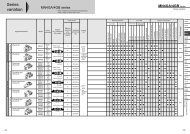
<strong>Positioning</strong> <strong>Systems</strong> Linear Motor Components 4. Linear Motor Components 4.1 Linear Motors, LMS Series HIWIN synchronous LMS linear motors are the powerhouses of linear drives and are characterized by a particularly high power density and minimal cogging. The three-phase motors consist of a primary part (forcer) with a wound armature core and a secondary part with permanent magnets (stators). Any length of stroke required can be achieved by combining several stators. 3-phase High force Exceptional acceleration Low cogging Any length stroke Several forcers possible on one stator Table 4.1 Specifications for Linear Motors, LMS Series Note: Values in the table refer to operation without forced cooling Force (N) 2000 1000 0 Force Chart for LMS Linear Motors 470 180 peak force continuous force 600 220 900 340 LMS13 LMS23 LMS27 LMS37 LMS47 LMS57 LMS67 Linear motor type Symbol Unit LMS13 LMS23 LMS27 LMS37 LMS37L LMS47 LMS47L LMS57 LMS57L LMS67 LMS67L Peak force for 1 second Fp N 470 600 900 1250 1250 1700 1700 2000 2000 2500 2500 Continuous force (at 80 °C) Fc N 180 220 340 475 475 650 650 780 780 950 950 Peak current for 1 second Ip A (rms) 12,3 10,5 10,5 10,5 21,0 10,5 21,0 10,5 21,0 10,5 21,0 Continuous force (at 80 °C) Ic A (rms) 4,1 3,5 3,5 3,5 7,0 3,5 7,0 3,5 7,0 3,5 7,0 Force constant Kf N/A (rms) 44 61 97 136 68 186 96 223 112 271 136 Attraction force Fa N 805 1350 2036 2850 2850 4071 4071 4885 4885 5700 5700 Max. winding temperature Tmax °C 100 100 100 100 100 100 100 100 100 100 100 Electric time constant Ke ms 9,8 11,4 10,8 10,8 10,8 11,1 11,1 11,2 11,2 11,3 11,3 Resistance (per phase at 25 °C) R 25 � 1,7 2,3 3,1 4,3 1,0 5,6 1,3 6,5 1,6 7,4 1,9 Inductance (per phase) L mH 33 55 32 45 10 62 15 73 18 84 21 Pole pitch 2� mm 32 32 32 32 32 32 32 32 32 32 32 Bending radius of motor cable Rbend mm 37,5 37,5 37,5 37,5 37,5 37,5 37,5 37,5 37,5 37,5 37,5 Back EMF constant Kv Vrms/(m/s) 26 43 51 71 41 101 59 121 61 141 71 Motor constant (at 25°C) Km N/� W 19,4 23,1 31,8 38,0 38,0 45,4 45,5 50,7 50,7 57,6 57,6 Thermal resistance Rth °C/W 0,33 0,33 0,46 0,40 0,40 0,30 0,30 0,26 0,26 0,23 0,23 Thermal circuit breakers 100 °C, bimetal (opener), DC 12 V/6 A, DC 24 V/3 A Max. DC-bus voltage V 750 750 750 750 750 750 750 750 750 750 750 Mass of forcer Mf kg 1,8 2,7 4,1 5,9 5,9 8,0 8,0 9,4 9,4 10,8 10,8 Own mass of stator Ms kg/m 4,2 6,2 6,2 8,2 8,2 11,5 11,5 13,7 13,7 15,9 15,9 Width of stator Ws mm 60 80 80 100 100 130 130 150 150 170 170 Length of stator / Dimension N Ls mm 192 mm/N=2, 256/N=3, 320 mm/N=4, 384 mm/N=5, 448 mm/N=6, 512 mm/N=7 Distance between fixing holesgen As mm 45 65 65 85 85 115 115 135 135 155 155 Height of total system H mm 55,2 55,2 57,4 57,4 57,4 57,4 57,4 57,4 57,4 57,4 57,4 1250 475 1700 650 2000 780 2500 950
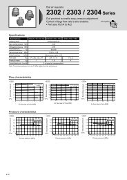
4.1.1 Dimensions for LMS Linear Motors Dimensions for LMS13 Linear Motors Dimensions for LMS23 Linear Motors Dimensions for LMS27 Linear Motors Dimensions for LMS37 Linear Motors All values in mm