Optimization and Computational Fluid Dynamics - Department of ...
Optimization and Computational Fluid Dynamics - Department of ...
Optimization and Computational Fluid Dynamics - Department of ...

You also want an ePaper? Increase the reach of your titles
YUMPU automatically turns print PDFs into web optimized ePapers that Google loves.
6 Numerical <strong>Optimization</strong> for Advanced Turbomachinery Design 181<br />
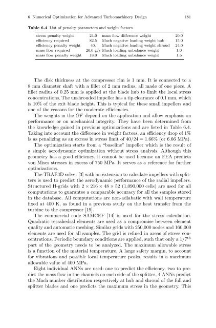
Table 6.4 List <strong>of</strong> penalty parameters <strong>and</strong> weight factors<br />
stress penalty weight 24.0 mass flow difference weight 20.0<br />
efficiency required 82.5 Mach negative loading weight hub 15.0<br />
efficiency penalty weight 40. Mach negative loading weight shroud 24.0<br />
mass flow required 20.0 g/s Mach loading unbalance weight 1.0<br />
mass flow penalty weight 18.0 Mach loading unbalance weight 1.5<br />
The disk thickness at the compressor rim is 1 mm. It is connected to a<br />
8 mm diameter shaft with a fillet <strong>of</strong> 2 mm radius, all made <strong>of</strong> one piece. A<br />
fillet radius <strong>of</strong> 0.25 mm is applied at the blade hub to limit the local stress<br />
concentrations. The unshrouded impeller has a tip clearance <strong>of</strong> 0.1 mm, which<br />
is 10% <strong>of</strong> the exit blade height. This is typical for these small impellers <strong>and</strong><br />
one <strong>of</strong> the reasons for the moderate efficiencies.<br />
The weights in the OF depend on the application <strong>and</strong> allow emphasis on<br />
performance or on mechanical integrity. They have been determined from<br />
the knowledge gained in previous optimizations <strong>and</strong> are listed in Table 6.4.<br />
Taking into account the difference in weight factors, an efficiency drop <strong>of</strong> 1%<br />
is as penalizing as an excess in stress limit <strong>of</strong> 40/24 = 1.66% (or 6.66 MPa).<br />
The optimization starts from a “baseline” impeller which is the result <strong>of</strong><br />
a simple aerodynamic optimization without stress analysis. Although this<br />
geometry has a good efficiency, it cannot be used because an FEA predicts<br />
von Mises stresses in excess <strong>of</strong> 750 MPa. It serves as a reference for further<br />
optimizations.<br />
The TRAF3D solver [3] with an extension to calculate impellers with splitters<br />
is used to predict the aerodynamic performance <strong>of</strong> the radial impellers.<br />
Structured H-grids with 2 × 216 × 48 × 52 (1,090,000 cells) are used for all<br />
computations to guarantee a comparable accuracy for all the samples stored<br />
in the database. All computations are non-adiabatic with wall temperature<br />
fixed at 400 K, as found in a previous study on the heat transfer from the<br />
turbine to the compressor [19].<br />
The commercial code SAMCEF [14] is used for the stress calculation.<br />
Quadratic tetrahedral elements are used as a compromise between element<br />
quality <strong>and</strong> automatic meshing. Similar grids with 250,000 nodes <strong>and</strong> 160,000<br />
elements are used for all samples. The grid is refined in areas <strong>of</strong> stress concentrations.<br />
Periodic boundary conditions are applied, such that only a 1/7 th<br />
part <strong>of</strong> the geometry needs to be analyzed. The maximum allowable stress<br />
is a function <strong>of</strong> the material temperature. A large safety margin, to account<br />
for vibrations <strong>and</strong> possible local temperature peaks, results in a maximum<br />
allowable value <strong>of</strong> 400 MPa.<br />
Eight individual ANNs are used: one to predict the efficiency, two to predict<br />
the mass flow in the channels on each side <strong>of</strong> the splitter, 4 ANNs predict<br />
the Mach number distribution respectively at hub <strong>and</strong> shroud <strong>of</strong> the full <strong>and</strong><br />
splitter blades <strong>and</strong> one predicts the maximum stress in the geometry. This