Combivert F0_Spain.indb
Combivert F0_Spain.indb
Combivert F0_Spain.indb

Create successful ePaper yourself
Turn your PDF publications into a flip-book with our unique Google optimized e-Paper software.
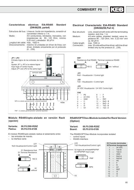
COMBIVERT <strong>F0</strong>Características eléctricas EIA-RS485 Standard(DIN 66259, parte4)Estructura del bus: Línea en bucle con impedancia, conexión alconvertidor inferior a 1 m.Medio:4/2 conductores, blindados, trenzados, conimpedancias de 80…120 Ohm, mínimo0,22 mm 2 y alrededor 60 pF/mLongitud del cable: máx.. 1000 mDireccionamiento: máximo 32 unidades sin driver de línea; condriver, limitado únicamente por el protocolo(0…239).Electrical Characteristic EIA-RS485 Standard(DIN 66259,Part 4)Bus structure:Medium:Cable length:Connection:Line, closed at both ends with the terminatingresistor, stub line 1 m4/2-wire cables, shielded, twisted, wave impedance80…120 Ohm, min. 0.22 mm 2 andca. 60 pF/mmax. 1000 mmax. 32 units without line driver, with line driverlimited only by the protocol (0…239).JP1 / JP2Entrada lógica de las entradas de mando.Ajustar JP1 y JP2 a la misma lógica!Input logic of control inputs.Adjust JP1 and JP2 to the same logic!00.<strong>F0</strong>.021-0209PNPNPNJP1 JP2LD11 LD3LD2SW1BSW1Resistencia fi nal RS485 / Terminal resistance RS485A B A150 Ω sin / withoutLD1RxD - Visualización / Control lightCN2LD2TxD - Visualización / Control lightCN21 2 3 4 5 6 7 8 9 10 11 12 13 14LD324 VDC Visualización / 24 VDC Control light+24 VDC–NPN–no aislado galvánicamente / potential separated– 24 VDC+PNP – no aislado galvánicamente / potential separatedRS485CN21 – PE 8 – F2 – 24 VDC 9 – R3 – GND 10 – RST4 – I1 11 – RxD - B5 – I2 12 – RxD - A6 – I3 13 – TxD - B7 – ST 14 – TxD - AMódulo RS485/opto-aislado en versión Rack(opción)RS485/OPTOiso-Module isolated for Rack Version(Option)Variante:Pletina:00.<strong>F0</strong>.D00-R20Z05.<strong>F0</strong>.010-0109Variant:Board:00.<strong>F0</strong>.D00-R20Z05.<strong>F0</strong>.010-0109El módulo RS485/opto-aislado realiza el aislamiento entre:– las entradas de mando.– la interface serieThe RS485/OPTOiso-Module incorporates isolated– control inputs– RS485-Interface.LD1RxD-Visualización/Control LightS1 Resistencia fi nalS1 Terminal ResistanceB ABA150 ΩsinwithoutLD2TxD-Visualizacións/Control LightS2 lógica de entradaNPN/PNPS2 NPN/PNP Input LogicX3PNPNPNX3 Función terminalesX3Terminal Assignment1 – 24 VDC2 – TxD-B3 – TxD-A4 – GND5 – RxD-A6 – RxD-B7 – PE8 – F9 – R10 – ST11 – RST12 – I313 – I214 – I185