253/3 - Wertherint.de
253/3 - Wertherint.de
253/3 - Wertherint.de

You also want an ePaper? Increase the reach of your titles
YUMPU automatically turns print PDFs into web optimized ePapers that Google loves.
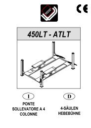
Lato comando<br />
Command si<strong>de</strong><br />
Côté comman<strong>de</strong>s<br />
Steuerseite<br />
Lado mando<br />
Lato anteriore<br />
Front si<strong>de</strong><br />
Côté avant<br />
Vor<strong>de</strong>rseite<br />
Lado anterior<br />
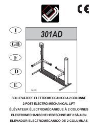
Fig.4- Abb.4<br />
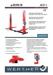
Fig.5 - Abb.5<br />
10<br />
3<br />
Lato posteriore<br />
Rear si<strong>de</strong><br />
Côté arrière<br />
Rückseite<br />
Lado posterior<br />
5<br />
2<br />
1<br />
Lato servizio<br />
Service si<strong>de</strong><br />
Côté <strong>de</strong> service<br />
Service-Seite<br />
Lado servicio<br />
4<br />
CAP.1. DESCRIZIONE DELLA<br />
MACCHINA<br />
lI sollevatore elettromeccanico a 2 colonne <strong>253</strong> è fisso, cioè ancorato al<br />
suolo ed è progettaoi e costruito per il sollevamento e lo stazionamento<br />
in quota di autoveicoli e furgoni.<br />
Il sollevatore è composto, principalmente da :<br />
- gruppo struttura fissa ( basamento + colonne)<br />
- gruppo mobile ( carrello + bracci )<br />
- gruppi di sollevamento;<br />
- quadro comando<br />
- sicurezze.<br />
In figura 3 sono indicate le varie parti che compongono il sollevatore e<br />
le zone di lavoro consentite e riservate al personale ad<strong>de</strong>tto, attorno al<br />
sollevatore stesso.<br />
Lato comando: è il lato <strong>de</strong>l sollevatore che compren<strong>de</strong> la zona riservata<br />
all’operatore in cui si acce<strong>de</strong> al quadro comandi<br />
Lato servizio: è il lato opposto a quello comando.<br />
Lato anteriore: è il lato braccio lungo.<br />
Lato posteriore: è il lato braccio corto.<br />
GRUPPO STRUTTURA FISSA (Fig.5)<br />
E’ costituito da :<br />
Un Basamento (1) costruito in tubi di acciaio saldati, con fori per il fissaggio<br />
al suolo mediante tasselli ad espansione (ve<strong>de</strong>re cap.4 “Installazione“)<br />
e fori filettati per il fissaggio tramite bullonatura <strong>de</strong>lla piastra di base <strong>de</strong>lla<br />
colonna.All’interno <strong>de</strong>l basamento è posizionata la barra di trasmissione<br />
(2) che trasmette il moto dalla colonna motore (3) alla colonna servizio (4).<br />
Nella parte superiore <strong>de</strong>l basamento è fissata la pedana (5) di copertura in<br />
lamiera striata .<br />
2 Colonne in tubolare di acciaio alla cui base è saldata una piastra<br />
forata per il fissaggio al basamento mediante bullonatura.<br />
All’interno di ogni colonna si trovano i gruppi mobili di sollevamento<br />
<strong>de</strong>ll’automezzo.<br />
CHAPTER 1. DESCRIPTION OF THE<br />
MACHINE<br />
2 post electro-mechanical lift is anchored to the ground, and is <strong>de</strong>signed<br />
and manufactured for lifting vehicles and vans and holding them<br />
in an elevated position.<br />
The lift mainly comprises:<br />
- fixed structural unit (base and post)<br />
- mobile unit (carriage and arms)<br />
- lift units<br />
- control panel<br />
- safety <strong>de</strong>vices.<br />
Figure 3 illustrates the various parts making up the lift, as well as the permitted<br />
work areas reserved for authorised personnel around the machine.<br />
Command si<strong>de</strong>: the si<strong>de</strong> of the rack which inclu<strong>de</strong>s the area reserved<br />
for the operator with access to the control panel<br />
Service si<strong>de</strong>: the si<strong>de</strong> opposite to the command si<strong>de</strong>.<br />
Front: long arm si<strong>de</strong>.<br />
Rear: short arm si<strong>de</strong>.<br />
FIXED STRUCTURE GROUP (Fig.5)<br />
Comprises:<br />
Base (1) ma<strong>de</strong> of wel<strong>de</strong>d steel tubes, with holes for anchoring to the<br />
ground by screw anchors (see Chap. 4 “ Installation “) and bushes<br />
with threa<strong>de</strong>d holes for bolting on the post baseplates.<br />
A roller chain (2) is located insi<strong>de</strong> the base to transmit drive from the<br />
motor post (3) to the service post (4).<br />
Two base cover plates (5) in chequered steel are fixed to the upper<br />
part of the base.<br />
2 pressed steel plate posts, with wel<strong>de</strong>d baseplate pre-drilled for bolting<br />
to un<strong>de</strong>rlying structure.<br />
Each post houses the mobile units for lifting the vehicle.