253/3 - Wertherint.de
253/3 - Wertherint.de
253/3 - Wertherint.de

Create successful ePaper yourself
Turn your PDF publications into a flip-book with our unique Google optimized e-Paper software.
Fig.6 - Abb.6<br />
Fig.7 - Abb.7<br />
Fig.8 - Abb.8<br />
12<br />
3<br />
1<br />
12<br />
13<br />
8<br />
2<br />
7<br />
6<br />
4<br />
2<br />
10<br />
9<br />
11<br />
5<br />
5<br />
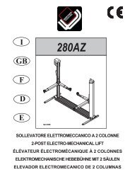
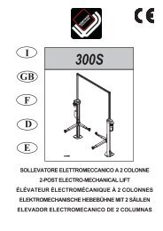
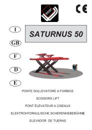
GRUPPI DI SOLLEVAMENTO (Fig.6)<br />
Ciascuno è costituito da :<br />
un carrello (1) in lamiera di acciaio saldata, collegato nella parte inferiore,<br />
mediante flange e perni, ai bracci sollevamento.<br />
Al centro, il carrello è collegato alla madrevite (2) che, tramite il movimento<br />
<strong>de</strong>lla vite, ne permette il sollevamento (3-4).<br />
Nella parte laterale esso è collegato, mediante viti e basette, ai pattini<br />
di scorrimento che lo mantengono in guida .<br />
Due bracci telescopici di cui uno lungo (3) e uno corto (4) (snodato<br />
nel mo<strong>de</strong>llo 252), costruiti in tubolare di acciaio e recanti ad una<br />
estremità il piattello regolabile (5) in altezza per la presa <strong>de</strong>lla macchina<br />
e dalla parte opposta il foro di collegamento con il carrello<br />
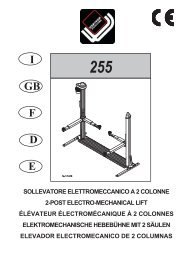
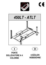
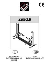
GRUPPO DI TRASMISSIONE (Fig.7)<br />
E’ composto da due viti elicoidali (2) in acciaio speciale sospese nella<br />
parte superiore <strong>de</strong>lla colonna mediante un cuscinetto assiale (6) ed uno<br />
reggispinta (7).<br />
La vite <strong>de</strong>lla colonna motrice è azionata da un dispositivo composto da<br />
un motore elettrico (8), pulegge (9) e cinghie trapezoidali (10) che comunicano<br />
il moto all’altra vite mediante trasmissione a cardano.<br />
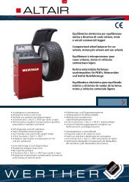
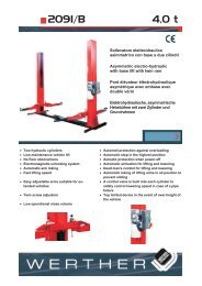
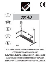
QUADRO DI COMANDO (Fig.8)<br />
Sul pannello <strong>de</strong>l quadro elettrico di comando sono installati :<br />
L’interrutore generale (11)<br />
Il pulsante di salita (12)<br />
Il pulsante di discesa (13)<br />
SICUREZZE<br />
Le sicurezze sono costituite da :<br />
Un sistema di bloccaggio bracci.<br />
salvapiedi elettrici.<br />
una sicurezza meccanica in caso di usura <strong>de</strong>lla chiocciola portante.<br />
I finecorsa di estremità colonna.<br />
Le sicurezze elettriche.<br />
Queste sicurezze saranno sviluppate in maggior <strong>de</strong>ttaglio nei seguenti<br />
capitoli.<br />
LIFTING UNITS (Fig.6)<br />
Each comprises:<br />
wel<strong>de</strong>d sheet steel carriage (1) connected in the lower part to the lifting<br />
arms by flanges and pins.<br />
The carriage is connected at the centre to the lead nut (2), which provi<strong>de</strong>s<br />
lifting motion by travelling on the lead screws.<br />
The carriage is laterally joined by pins to the sliding shoes which<br />
keep it on the sli<strong>de</strong> ways.<br />
Two telescoping arms (one long, 3 and one short, 4) ma<strong>de</strong> from tubular<br />
steel, each with a height adjustable disk support plate (5) at one<br />
end for picking up the vehicle, and a hole at the other end for connection<br />
to the carriage.<br />
TRANSMISSION UNIT (Fig.7)<br />
The unit comprises two special-steel helical screws (2) suspen<strong>de</strong>d in<br />
the upper part of the post by an axial bearing (6) and a thrust bearing<br />
(7).<br />
The lead screw in the drive post is operated by a system comprising an<br />
electric motor (8), pulleys (9) and Vee belts (10) which transmit drive to<br />
the other lead screw by means of a chain and chain sprocket transmission<br />
insi<strong>de</strong> the base.<br />
CONTROL PANEL (Fig.8)<br />
The electric control panel inclu<strong>de</strong>s:<br />
Master switch (11)<br />
“LIFT” button (12)<br />
“DESCEND” button (13)<br />
SAFETY DEVICES<br />
These inclu<strong>de</strong>:<br />
arm lock system<br />
electric footguards<br />
safety cable for carriage level differences.<br />
post limit switch.<br />
electrical safety <strong>de</strong>vices<br />
These features will be <strong>de</strong>alt with in greater <strong>de</strong>pth in the following chapters.