253/3 - Wertherint.de
253/3 - Wertherint.de
253/3 - Wertherint.de

Create successful ePaper yourself
Turn your PDF publications into a flip-book with our unique Google optimized e-Paper software.
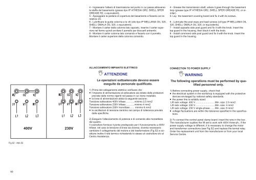
Fig.52 - Abb.52<br />
50<br />
400V<br />
230V<br />
4 - Ingrassare l’albero di trasmissione nel punto in cui passa attraverso<br />
la staffa <strong>de</strong>l basamento (grasso tipo IP ATHESIA GR2, SHELL SPER<br />
GREASE R2, o equivalenti).<br />
5 - Appoggiare la pedana di copertura <strong>de</strong>l basamento e fissarla con le<br />
relative viti.<br />
6 - Lubrificare le gui<strong>de</strong> colonna e le viti (olio tipo IP MELLANIA OIL 320,<br />
SHELL OMALA OIL 320, o equivalenti).<br />
7 - Montare il carter <strong>de</strong>lla colonna lato opposto, inserire il carter superiore<br />
nel fermo quindi avvitare il pomello per bloccarli antrambi.<br />
8 - Montare il carter colonna lato comando e fissarlo con il pomello.<br />
Montare il carter superiore <strong>de</strong>lla colonna comando.<br />
ALLACCIAMENTO IMPIANTO ELETTRICO<br />
ATTENZIONE<br />
Le operazioni sottoelencate <strong>de</strong>vono essere<br />
eseguite da personale qualificato.<br />
1) Prima <strong>de</strong>l collegamento elettrico verificare che :<br />
l’impianto di alimentazione al sollevatore sia dotato <strong>de</strong>lle protezioni<br />
previste dalle norme vigenti nel paese in cui viene installato.<br />
la linea di alimentazione abbia la seguente sezione :<br />
Tensione sollevatore 400V trifase:............minimo 2,5 mm2<br />
Tensione sollevatore 230V trifase:............minimo 4 mm2<br />
Tensione sollevatore 230V monofase:...... minimo 6 mm2<br />
le oscillazioni di tensione rientrino nel campo di tolleranza previsto<br />
dalle specifiche.<br />
2) Eseguire l’allacciamento di potenza e di comando alla morsettiera<br />
<strong>de</strong>l quadro.<br />
Il costruttore fornisce il ponte predisposto per il funzionamento a 400V<br />
trifase; nel caso la tensione di linea sia diversa, diventa necessario<br />
cambiare il collegamento <strong>de</strong>l motore e <strong>de</strong>l trasformatore (Fig.52) e sostituire<br />
inoltre il relè termico richie<strong>de</strong>ndo lo stesso al costruttore e/o al<br />
Centro Assistenza.<br />
4 - Grease the transmission shaft, where it goes through the basement<br />
loop (grease type IP ATHESIA GR2, SHELL SPER GREASE R2, or similar).<br />
5- Lay the basement covering board and fix it with its screws..<br />
6 - Lubricate the post ways and lead screws (oil type IP MELLANIA OIL<br />
320, SHELL OMALA OIL 320, or equivalents).<br />
7 - Install opposite si<strong>de</strong> post guard and fix it with the knob. Insert the<br />
top guard in the housing, then block it with the knob.<br />
8 - Install command si<strong>de</strong> post guard and fix it with the knob. Insert the<br />
top guard in the housing.<br />
CONNECTION TO POWER SUPPLY<br />
WARNING<br />
The following operations must be performed by qualified<br />
personnel only.<br />
1) Before connecting power supply, check that:<br />
the electrical system in the workshop is equipped with the protective<br />
<strong>de</strong>vices envisaged by national safety standards.<br />
the power line is suitably sized:<br />
Lift rack voltage: 400 V.............................Min. size: 2.5 mm2<br />
Lift rack voltage: 230 V.............................Min. size: 4 mm2<br />
Lift rack voltage: 230 V single-phase. ......Min. size: 6 mm2<br />
voltage fluctuations are within the tolerance specified in the specifications.<br />
2) To connect the control panel clamp board: insert the wire in the box .<br />
The manufacturer supllies the lift set to work with 400V three-ph.; if the<br />
power supply voltage is different, it is necessary to change the motor<br />
and transformer connections (see Fig.52) and replace the termal relay.<br />
Or<strong>de</strong>r the replacement unit from the manufacturer or from your local<br />
Service Centre.