253/3 - Wertherint.de
253/3 - Wertherint.de
253/3 - Wertherint.de

Create successful ePaper yourself
Turn your PDF publications into a flip-book with our unique Google optimized e-Paper software.
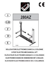
Fig.31 - Abb.31<br />
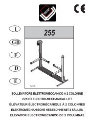
Fig.32 - Abb. 32<br />
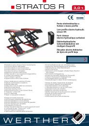
Fig.34 - Abb.34<br />
34<br />
N N<br />
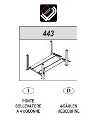
Fig.33 - Abb.33<br />
MONTAGGIO<br />
ATTENZIONE<br />
DURANTE IL MONTAGGIO NON É AMMESSO<br />
NESSUN ESTRANEO AI LAVORI<br />
MONTAGGIO BASAMENTO<br />
1 - Posizionare il basamento nel luogo prescelto per il montaggio.<br />
2 - Montare i due traversi laterali fissandoli al basamento mediante le<br />
viti TE M14x100 (fig.31). I traversi non sono reversibili e la loro posizione<br />
è contrassegnata nel punto “N”<br />
3 - Togliere i tappi di protezione dai fori <strong>de</strong>lla colonna e controllare che i<br />
filetti non siano danneggiati.<br />
4 - Usando un carrello elevatore (fig.32) appoggiare la colonna comando<br />
sulla parte sinistra <strong>de</strong>l basamento, visto dal lato anteriore.<br />
5 - Centrare la colonna sul basamento quindi inserire le relative spine<br />
come indicato in fig.33<br />
6 - Inserire nella parte anteriore interna e posteriore interna di ogni colonna<br />
i piattini di sgancio <strong>de</strong>l sistema di sicurezza <strong>de</strong>i bracci, come indicato<br />
in fig.34.<br />
INSTALLATION<br />
CAUTION<br />
DURING INSTALLATION NO AUTHORIZED PEOPLE<br />
IS ALLOWED<br />
BASE ASSEMBLING<br />
1 - Position the basement in the place chosen to assemble the machine.<br />
2- Mount the two si<strong>de</strong> supports fixing them to the basement using HH<br />
screws M14x100 (fig. 31). The Si<strong>de</strong> supports are not interchangeable<br />
and their position is marked in the “N” point.<br />
3- Remove the protection caps from the post drills and check the<br />
threads are not damaged.<br />
4- Using a fork truck (fig. 32), set the post on the left si<strong>de</strong> of the basement<br />
(seen from the front si<strong>de</strong>).<br />
5- Centre the post on the basement, then insert the pins as shown in<br />
fig. 33.<br />
6 -Insert the release metal strips of the arms security system in the inner<br />
front and rear si<strong>de</strong>s of the post, as shown in fig. 34.