JDLink™ Universal MTG Install Kit - StellarSupport - John Deere
JDLink™ Universal MTG Install Kit - StellarSupport - John Deere
JDLink™ Universal MTG Install Kit - StellarSupport - John Deere

Create successful ePaper yourself
Turn your PDF publications into a flip-book with our unique Google optimized e-Paper software.
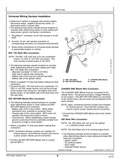
<strong>Universal</strong> Wiring Harness <strong>Install</strong>ation<br />
• Determine if vehicle is equipped with positive battery<br />
disconnect switch, negative disconnect switch, no<br />
disconnect switch or power relay.<br />
• The following instructions indicate several locations to<br />
consider when determining where to route cabling and<br />
make power, ground, and ignition connections.<br />
1. Plug Molex connector on the Cab harness in to the<br />
<strong>MTG</strong>.<br />
2. Connect 10 pin cab harness connector to<br />
corresponding connector on <strong>Universal</strong> wiring harness.<br />
3. Route wiring connections on <strong>Universal</strong> wiring harness<br />
to appropriate location on vehicle.<br />
BAT +VE (Red) Wire Connection<br />
NOTE: The BAT +VE (red) wire is for the unswitched<br />
(main) +12 VDC or +24 VDC connection. This<br />
wire provides constant power to the <strong>MTG</strong>.<br />
• The following indicates several locations to consider<br />
when determining where to route cabling and make<br />
BAT +VE (Red) wire connection.<br />
Alternator (Constant 12 VDC or 24 VDC)<br />
High side of vehicle main wiring bus.<br />
Battery side of the fuse box (not the load side).<br />
Battery side of the ignition switch.<br />
• Attach a supplied 7.5 amp fuse before making the final<br />
connection.<br />
• Connect the BAT +VE (red) wire to an unswitched +12<br />
VDC or +24 VDC power source, such as the hot side<br />
of the vehicle main wiring bus, the battery side of the<br />
ignition switch, or the battery side of the fuse block (not<br />
the load side).<br />
BAT RETURN (Black) Wire Connection<br />
• The following indicates several locations to consider<br />
when determining where to route cabling and BAT<br />
RETURN (Black) wire connection.<br />
Battery side of the cutout switch. (Must obtain<br />
permission from customer to connector here).<br />
Chassis side of the cutout switch. (<strong>MTG</strong> does not<br />
operate if the disconnect switch is open).<br />
Good ground. (When establishing a good chassis<br />
ground, avoid areas that are potentially isolated from<br />
ground by a hinge or some welds).<br />
• Attach a supplied 7.5 amp fuse before making final<br />
connection.<br />
NOTE: Sometimes thermal couplers are mistaken for<br />
chassis ground. Avoid thermal couplers and ensure<br />
a good, proper chassis ground connection.<br />
• Connect the BAT RETURN (Black) wire to a good<br />
ground (BAT).<br />
PFP10491 (08OCT10) 8<br />
BPF10159<br />
A—BAT +VE (Red)<br />
B—BAT RETURN (Black)<br />
C—CHASSIS GND (Black)<br />
D—Fuses<br />
CHASSIS GND (Black) Wire Connection<br />
The CHASSIS GND (Black) must be connected to the<br />
vehicle frame. This ground provides a voltage reference<br />
for the system. If the BAT RETURN (Black) is connected<br />
to the vehicle frame, the two wires can be attached at the<br />
same location.<br />
NOTE: Again, sometimes thermal couplers are mistaken<br />
for chassis ground. Avoid thermal couplers and<br />
ensure a good, proper chassis ground connection.<br />
• Connect the CHASSIS GND (Black) wire to the vehicle<br />
frame.<br />
IGN (Red) Wire Connection<br />
NOTE: The IGN (Red) wire can go to the ignition<br />
or a switched power source.<br />
NOTE: The IGN (Red) wire is for sensing engine hours.<br />
• The following indicates several locations to consider<br />
when determining where to route cabling and make IGN<br />
(red) wire connection.<br />
Ignition switch.<br />
Oil pressure switch.<br />
Hour meter.<br />
Switched Power Source<br />
Continued on next page JS56696,00008D1 1915SEP101/2<br />
PC12737 —UN—24AUG10<br />
101110<br />
PN=10