technical & service manual dc inverter multi-system air conditioner
technical & service manual dc inverter multi-system air conditioner
technical & service manual dc inverter multi-system air conditioner

You also want an ePaper? Increase the reach of your titles
YUMPU automatically turns print PDFs into web optimized ePapers that Google loves.
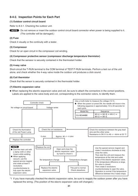
8-4-2. Inspection Points for Each Part<br />
(1) Outdoor control circuit board<br />
Refer to 8-3-1. Checking the outdoor unit.<br />
NOTE<br />
Do not remove or insert the outdoor control circuit board connector when power is being supplied to it.<br />
(The controller will be damaged.)<br />
(2) Fuse<br />
Check it visually or the continuity with a tester.<br />
(3) Compressor<br />
Check for an open circuit in the compressor coil winding.<br />
(4) Compressor protective sensor (compressor discharge temperature thermistor)<br />
Check that the senseor is securely contained in the thermostart holder.<br />
(5) 4-way valve<br />
Short-circuit the T-RUN terminal to the COM terminal of TEST/T-RUN terminals. Perfrom a test run of the unit<br />
alone, and check whether the 4-way valve inside the outdoor unit produces a click sound.<br />
(6) Coil thermistor<br />
Check that the sensor is securely contained in the thermostat holder.<br />
(7) Electric expansion valve<br />
When replacing the electric expansion valve and coil, be sure to attach the connectors in the correct positions.<br />
Labels are applied to the valve body and coil, corresponding to the connector colors, to identify them.<br />
No voltage on circuit board<br />
*1<br />
Check the illumination<br />
of the red Power Lamp.<br />
Replace the controller.<br />
NOTE<br />
Cool the main unit with<br />
a damp cloth or other<br />
means while welding.<br />
When applying<br />
vacuum, use the<br />
special <strong>service</strong> magnet<br />
and rotate at least 5<br />
revolutions<br />
counterclockwise to<br />
fully open the electric<br />
expansion valve.<br />
Controller check<br />
0 ohm<br />
Replace the coil.<br />
Voltage varies<br />
Check the coil resistance.<br />
*1<br />
Open and close the<br />
electric expansion valve<br />
by hand to check it.<br />
No temperature change Temperature changes<br />
Replace the electric<br />
expansion valve.<br />
Approx. 46 +/– 4 ohm<br />
31<br />
Use a <strong>multi</strong>-meter to measure the voltage (12 V).<br />
When the power is turned ON, the needle will move in the<br />
following seguence in approximately 10 to 20 seconds for<br />
each point.<br />
Model No. Sequence<br />
MV-A MV-B MV-C<br />
CU-5E34NBE<br />
MV-D MV-E<br />
This part is normal.<br />
Check elsewhere.<br />
Check the resistance between the gray lead<br />
wire and the other wires.<br />
Resistance is OK if it is 46 +/– 4ohm at 20 °C<br />
Use the special <strong>service</strong> magnet and<br />
rotate 5 revolutions clockwise to fully<br />
close the valve.<br />
Then start the unit and measure the<br />
temperature at the inlet and outlet<br />
tubes of the electric expansion valve.<br />
If the temperature difference is large,<br />
the valve is closed.<br />
Then rotate 5 revolutions<br />
counterclockwise to open the valve.<br />
Operation is normal if the temperature<br />
difference between the 2 tubes drops.<br />
If you have <strong>manual</strong>ly checked the electric expansion valve, be sure to reapply the outdoor power after you have<br />
replaced the wiring. (The position of the elecric expansion valve will changed.)