technical & service manual dc inverter multi-system air conditioner
technical & service manual dc inverter multi-system air conditioner
technical & service manual dc inverter multi-system air conditioner

You also want an ePaper? Increase the reach of your titles
YUMPU automatically turns print PDFs into web optimized ePapers that Google loves.
1-5. Additional Materials Required for Installation<br />
1. Refrigeration (armored) tape<br />
2. Insulated staples or clamps for connecting wire<br />
(See local codes)<br />
3. Putty<br />
4. Refrigeration lubricant<br />
5. Clamps or saddles to secure refrigerant tubing<br />
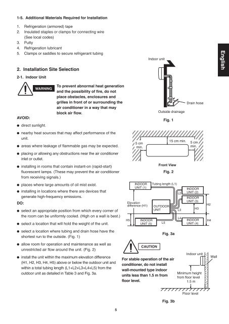
2. Installation Site Selection<br />
2-1. Indoor Unit<br />
AVOID:<br />
WARNING<br />
� direct sunlight.<br />
To prevent abnormal heat generation<br />
and the possibility of fire, do not<br />
place obstacles, enclosures and<br />
grilles in front of or surrounding the<br />
<strong>air</strong> <strong>conditioner</strong> in a way that may<br />
block <strong>air</strong> flow.<br />
� nearby heat sources that may affect performance of the<br />
unit.<br />
� areas where leakage of flammable gas may be expected.<br />
� placing or allowing any obstructions near the <strong>air</strong> <strong>conditioner</strong><br />
inlet or outlet.<br />
� installing in rooms that contain instant-on (rapid-start)<br />
fluorescent lamps. (These may prevent the <strong>air</strong> <strong>conditioner</strong><br />
from receiving signals.)<br />
� places where large amounts of oil mist exist.<br />
� installing in locations where there are devices that<br />
generate high-frequency emissions.<br />
DO:<br />
� select an appropriate position from which every corner of<br />
the room can be uniformly cooled. (High on a wall is best.)<br />
� select a location that will hold the weight of the unit.<br />
� select a location where tubing and drain hose have the<br />
shortest run to the outside. (Fig. 1)<br />
� allow room for operation and maintenance as well as<br />
unrestricted <strong>air</strong> flow around the unit. (Fig. 2)<br />
� install the unit within the maximum elevation difference<br />
(H1, H2, H3, H4, H5) above or below the outdoor unit and<br />
within a total tubing length (L1+L2+L3+L4+L5) from the<br />
outdoor unit as detailed in Table 3 and Fig. 3a.<br />
5<br />
5 cm<br />
min.<br />
INDOOR<br />
UNIT (1)<br />
Elevation<br />
difference (H1)<br />
H5<br />
INDOOR<br />
UNIT (5)<br />
Indoor unit<br />
CAUTION<br />
Outside drainage<br />
Fig. 1<br />
Front View<br />
Fig. 2<br />
Tubing length (L1)<br />
OUTDOOR<br />
UNIT<br />
L5<br />
Fig. 3a<br />
For stable operation of the <strong>air</strong><br />
<strong>conditioner</strong>, do not install<br />
wall-mounted type indoor<br />
units less than 1.5 m from<br />
floor level.<br />
Fig. 3b<br />
15 cm min.<br />
L2<br />
L3<br />
L4<br />
Drain hose<br />
5 cm<br />
min.<br />
INDOOR<br />
UNIT (2)<br />
INDOOR<br />
UNIT (3)<br />
H3<br />
INDOOR<br />
UNIT (4)<br />
Indoor unit<br />
Minimum height<br />
from floor level<br />
1.5 m<br />
Floor level<br />
H2<br />
H4<br />
Wall<br />
English