und Installationsanleitung (pdf) - dz-schliesstechnik gmbh
und Installationsanleitung (pdf) - dz-schliesstechnik gmbh
und Installationsanleitung (pdf) - dz-schliesstechnik gmbh

Sie wollen auch ein ePaper? Erhöhen Sie die Reichweite Ihrer Titel.
YUMPU macht aus Druck-PDFs automatisch weboptimierte ePaper, die Google liebt.
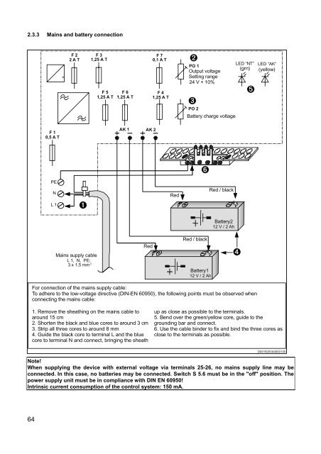
2.3.3 Mains and battery connection=F 22 A TF 31,25 A TF 51,25 A TF 61,25 A TF 70,1 A TF 41,25 A TÒPO 1Output voltageSetting range24 V + 10%ÓPO 2Battery charge voltageLED “NT” LED “AK”(grn) (yellow)ÕF 10,5 A TAK 1 AK 2PENL 1ÑRedMains supply cableL 1, N, PE;3 x 1,5 mm 2RedÖRed / blackBattery112 V / 2 AhRed / blackBattery212 V / 2 AhÔFor connection of the mains supply cable:To adhere to the low-voltage directive (DIN-EN 60950), the following points must be observed whenconnecting the mains cable:1. Remove the sheathing on the mains cable toaro<strong>und</strong> 15 cm2. Shorten the black and blue cores to aro<strong>und</strong> 3 cm3. Strip all three cores to aro<strong>und</strong> 8 mm4. Guide the black core to terminal L and the bluecore to terminal N and connect, bringing the sheathup as close as possible to the terminals.5. Bend over the green/yellow core, guide to thegro<strong>und</strong>ing bar and connect.6. Use the cable binder to fix and bind the three cores asclose to the terminals as possible.D0019203A0000100Note!When supplying the device with external voltage via terminals 25-26, no mains supply line may beconnected. In this case, no batteries may be connected. Switch S 5.6 must be in the "off" position. Thepower supply unit must be in compliance with DIN EN 60950!Intrinsic current consumption of the control system: 150 mA.64