und Installationsanleitung (pdf) - dz-schliesstechnik gmbh
und Installationsanleitung (pdf) - dz-schliesstechnik gmbh
und Installationsanleitung (pdf) - dz-schliesstechnik gmbh

Sie wollen auch ein ePaper? Erhöhen Sie die Reichweite Ihrer Titel.
YUMPU macht aus Druck-PDFs automatisch weboptimierte ePaper, die Google liebt.
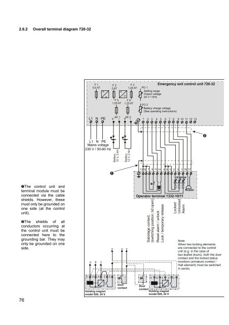
2.6.2 Overall terminal diagram 720-32F 10,5 ATL1 N PEF 22 ATF 51,25 AT=+ - + -F 31,25 ATF 61,25 ATAK 1 AK 2PO 1Setting rangeOutput voltage24 V +10%Emergency exit control unit 720-32PO 2Battery charge voltage(See operating instructions)1 2 3 4 5 6 7 8 9 10 11 12 13L1 N PEMains voltage230 V / 50-60 HzBattery12 V, 2 AHBattery12 V, 2 AH13 10 7 9 11 14 4 6 5 2 3 1 16 17rd gn yeThe control unit andterminal module must beconnected via the cableshields. However, thesemust only be gro<strong>und</strong>ed onone side (at the controlunit).The shields of allconductors occurring atthe control unit must beconnected here to thegro<strong>und</strong>ing bar. They mayonly be gro<strong>und</strong>ed on oneside.ABCD E FOperator terminal 1332-10/11Sabotage contact,(switching position: lid open)Reset alarm / unlockLock / temporary releaseLockedUnlockedAlarmBuzzerNote:When two locking elementsare connected to the controlunit (e.g. in the case oftwo-leafed doors), both the doorcontact and the locked statusmonitors (armature contact /Hall element) must be switchedin series.5 6 4 3 25 6 4 3 276Holding magnetmodel 828, 24 VDoorcontactDoorcontactHolding magnetmodel 828, 24 V