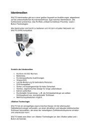
und Installationsanleitung (pdf) - dz-schliesstechnik gmbh
und Installationsanleitung (pdf) - dz-schliesstechnik gmbh
und Installationsanleitung (pdf) - dz-schliesstechnik gmbh

Sie wollen auch ein ePaper? Erhöhen Sie die Reichweite Ihrer Titel.
YUMPU macht aus Druck-PDFs automatisch weboptimierte ePaper, die Google liebt.
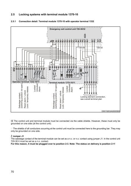
2.5 Locking systems with terminal module 1370-102.5.1 Connection detail: Terminal module 1370-10 with operator terminal 1332Emergency exit control unit 720-30/321 2 3 4 5 6 7 8 9 10 11 12 13 14 15 31 32 47 48720-30 720-3213 10 7 9 11 14 4 6 5 2 3 1 16 17rd gn yeBuzzer16 23 17 18 22 19 20 21 14 13 1 2 3 4 5 6rd gn yeSK3 12J1Operator terminal 1332-10/11Sabotage contact,(switching position: lid open)Reset alarm / unlockLock / temporary releaseLockedUnlockedAlarmTerminal module 1370-10/11Sabotage contact,(switching position: lid open)Reset alarm / unlockLock / temporary releaseLockedUnlockedAlarm7 8 9 10 11 12Locking element connection,see overall terminal planD0019203A0000500Œ The control unit and terminal module must be connected via the cable shields. However, these must only begro<strong>und</strong>ed on one side (at the control unit). The shields of all conductors occurring at the control unit must be connected here to the gro<strong>und</strong>ing bar. They mayonly be gro<strong>und</strong>ed on one side.Ž Jumper J1The sabotage contact of the terminal module can be set as a n.c. or n.o. contact using jumper J1. In the control unit720-30 it must be set as a n.o. contact.For this reason, it must be plugged over to position 2-3. Note: The status on delivery is position 2-1!70