Newport HT50 Operator's Manual
Newport HT50 Operator's Manual
Newport HT50 Operator's Manual

You also want an ePaper? Increase the reach of your titles
YUMPU automatically turns print PDFs into web optimized ePapers that Google loves.
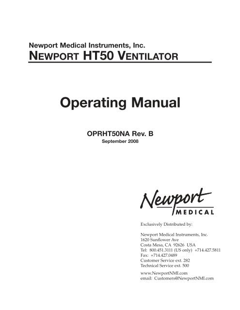
<strong>Newport</strong> Medical Instruments, Inc.<br />
NEWPORT <strong>HT50</strong> VENTILATOR<br />
Operating <strong>Manual</strong><br />
OPR<strong>HT50</strong>NA Rev. B<br />
September 2008<br />
Exclusively Distributed by:<br />
<strong>Newport</strong> Medical Instruments, Inc.<br />
1620 Sunflower Ave<br />
Costa Mesa, CA 92626 USA<br />
Tel: 800.451.3111 (US only) +714.427.5811<br />
Fax: +714.427.0489<br />
Customer Service ext. 282<br />
Technical Service ext. 500<br />
www.<strong>Newport</strong>NMI.com<br />
email: Customers@<strong>Newport</strong>NMI.com
<strong>HT50</strong> Operating <strong>Manual</strong> OPR<strong>HT50</strong>NA<br />
DATE REVISION PAGES EFFECTED<br />
OPR<strong>HT50</strong>NA B0908<br />
MANUAL REVISION HISTORY<br />
September 2007 A New release, for dual internal battery<br />
updates from OPR<strong>HT50</strong>B rev. D - 2-2,<br />
2-3, 2-4, 2-5, 2-6, 3-12, 3-13, 6-8, 7-2,<br />
7-3, 7-7, A-7<br />
September 2008 B Updated to include additional dual<br />
internal battery data, update intended<br />
use statement, refine cleaning and<br />
sterilization section
OPR<strong>HT50</strong>NA B0908<br />
TABLE OF CONTENTS<br />
Section 1 . . . . . . . . . . OPERATOR’S RESPONSIBILITY<br />
• Operator’s Responsibility for Patient Safety<br />
• Limitation of Liability<br />
• Warranty<br />
• Definitions<br />
• Typing Conventions<br />
• Warnings and Cautions<br />
• Factory Maintenance or Repair<br />
• Contact Information<br />
Section 2 . . . . . . . . . . SPECIFICATIONS<br />
• Intended Use<br />
• Symbols / Labeling Table<br />
• Controls / Alarms / Monitors<br />
• Hardware Requirements<br />
• Miscellaneous Specifications<br />
• Humidifier Specifications<br />
• Air / Oxygen Entrainment Mixer Specifications<br />
• Oxygen Blending Bag Kit Specifications<br />
Section 3 . . . . . . . . . . DESCRIPTION OF CONTROLS, INDICATORS,<br />
ALARMS & CONNECTORS<br />
• Front Panel Overview<br />
• Front Panel Controls & Indicators<br />
• Front Panel Alarms<br />
• Front Panel Message Display Window<br />
• Left Side Connectors<br />
• Right Side Connectors<br />
• Optional Accessories<br />
• User Set Up<br />
Section 4 . . . . . . . . . . THEORY OF OPERATION<br />
• General System Overview<br />
• A/CMV Mode (Assist/Control Mandatory Ventilation)<br />
• SIMV Mode (Synchronized Intermittent Mandatory<br />
Ventilation)<br />
• SPONT Mode (Spontaneous Ventilation)<br />
• Psupport (Pressure Support)<br />
• Pressure Control Ventilation<br />
• Volume Control Ventilation<br />
• Back-Up Ventilation
Section 5 . . . . . . . . . . VENTILATION SET UP & USE<br />
• Introduction<br />
• Assembling the Ventilator<br />
• Ventilator Set Up Procedure with<br />
Exhalation Valve Calibration<br />
• Patient Set Up Procedure<br />
• Built-in Humidifier (model <strong>HT50</strong>-H, <strong>HT50</strong>-HB)<br />
• Air / Oxygen Entrainment Mixer (Optional Accessory)<br />
• Oxygen Blending Bag Kit (Optional Accessory)<br />
Section 6 . . . . . . . . . . CLEANING & MAINTENANCE<br />
• Cleaning & Disinfecting<br />
• Maintenance<br />
• General Warnings<br />
Section 7 . . . . . . . . . . TROUBLESHOOTING<br />
• Introduction<br />
• Table 7-1 Alarms<br />
• Table 7-2 Built-in Humidifier<br />
• Table 7-3 General / Clinical<br />
• Table 7-4 Setting Limitation Messages<br />
Appendix A . . . . . . . . QUICK CHECK PROCEDURE<br />
• Introduction<br />
• Set Up<br />
• Standard Test Settings<br />
• Quick Check Procedure<br />
• Pass / Fail Check Off Sheet<br />
• Abbreviated Check Procedure<br />
Appendix B . . . . . . . . <strong>HT50</strong> ACCESSORIES<br />
• <strong>HT50</strong> Parts & Accessories<br />
Appendix C . . . . . . . . <strong>HT50</strong> HELP GUIDE<br />
• Questions & Answers<br />
ii OPR<strong>HT50</strong>NA B0908
1. OPERATOR’S RESPONSIBILITY<br />
OPR<strong>HT50</strong>NA B0908<br />
Operator’s Responsibility for Patient Safety . . . . . 1-1<br />
Limitation of Liability . . . . . . . . . . . . . . . . . . . . . . . 1-2<br />
Warranty . . . . . . . . . . . . . . . . . . . . . . . . . . . . . . . . . 1-2<br />
Definitions. . . . . . . . . . . . . . . . . . . . . . . . . . . . . . . . 1-3<br />
Typing Conventions . . . . . . . . . . . . . . . . . . . . . . . . 1-3<br />
Warnings and Cautions . . . . . . . . . . . . . . . . . . . . . 1-3<br />
Factory Maintenance or Repair . . . . . . . . . . . . . . 1-7<br />
Contact Information . . . . . . . . . . . . . . . . . . . . . . . . 1-7
OPERATOR’S RESPONSIBILITY FOR PATIENT SAFETY<br />
SECTION 1<br />
The Operating manual (p/n OPR<strong>HT50</strong>-NA) contains information<br />
intended to ensure safe and effective ventilator use. The label on<br />
the inside of the front panel cover door is meant to complement<br />
not replace the Operating manual.<br />
The design of the <strong>HT50</strong> ventilator, the Operating and Service<br />
manuals, and the labeling on the ventilator take into consideration<br />
that the purchase and use of the equipment is restricted to trained<br />
professionals, and that certain inherent characteristics of the<br />
ventilator are known to the operator. Instructions, warnings and<br />
caution statements are therefore limited to the specifics of the<br />
<strong>Newport</strong> <strong>HT50</strong>.<br />
Caution Federal law restricts this device to sale by or on the<br />
order of a physician.<br />
This manual excludes references to various hazards which are<br />
obvious to medical professionals and operators of this equipment,<br />
to the consequences of product misuse, and to potentially adverse<br />
effects in patients with abnormal conditions.<br />
When the <strong>HT50</strong> is used in home care and sub acute environments it<br />
is important that the primary caregiver has received training and has<br />
demonstrated competency in all equipment functions. A specific<br />
written care plan must be established by the attending physician.<br />
Transport of patients with the <strong>HT50</strong> requires that medical staff<br />
have a good working knowledge of the ventilator’s use and<br />
problem resolution. Proper emergency back-up equipment must<br />
be immediately available during transport.<br />
<strong>HT50</strong> operators must recognize their responsibility for<br />
implementing safety monitoring mechanisms which supply<br />
appropriate information on equipment performance and patient<br />
condition. Patient safety may be achieved through a wide variety<br />
of means such as electronic surveillance of equipment<br />
performance and patient condition. However, equipment<br />
surveillance should not replace direct observation of clinical signs.<br />
The <strong>HT50</strong> operator is solely responsible for selecting the<br />
appropriate level and method of patient monitoring.<br />
Product modification or misuse can be dangerous. <strong>Newport</strong><br />
Medical Instruments, Inc. (NEWPORT) disclaims all liability for the<br />
consequences of product alterations or modifications, as well as<br />
for the consequences which might result from the combination of<br />
this ventilator with other products, whether supplied by <strong>Newport</strong> or<br />
by other manufacturers, unless such a combination has been<br />
specifically endorsed by <strong>Newport</strong>.<br />
OPR<strong>HT50</strong>NA B0908 1-1
OPERATOR’S RESPONSIBILITY<br />
LIMITATION OF LIABILITY<br />
WARRANTY<br />
The liability of <strong>Newport</strong> Medical Instruments, Inc. (NEWPORT) is<br />
subject to and limited to the exclusive terms and conditions as set<br />
forth herein. Said liability is limited whether arising out of, or related<br />
to, the manufacture and sale of goods, their installation,<br />
demonstration, sales representation, use, performance, or<br />
otherwise. Any liability based upon product warranty, whether<br />
breach of warranty or otherwise, is limited regardless of any fault<br />
attributable to NEWPORT and the nature of the action (including<br />
breach of warranty, negligence, and strict liability).<br />
The expressed warranties are in lieu of all other warranties,<br />
expressed or implied, including, without limitation, warranties of<br />
merchantability, fitness for any purpose, or noninfringement.<br />
NEWPORT shall not be liable for any special incidental or<br />
consequential damages incurred by the buyer to a third party. The<br />
buyer shall not be entitled to make liability recoveries from<br />
NEWPORT due to such situations.<br />
The <strong>Newport</strong> <strong>HT50</strong> Ventilator is guaranteed to be free of defects<br />
for a period of two (2) years from date of delivery. The following are<br />
exceptions to this warranty:<br />
1. Defects caused by misuse, mishandling, tampering, or by<br />
modifications not authorized by <strong>Newport</strong> Medical Instruments,<br />
Inc. (NEWPORT) or its representatives.<br />
2. Rubber and plastic components and materials are guaranteed<br />
to be free of defects at time of delivery.<br />
3. The internal batteries are warranted for six months.<br />
Any product which proves to be defective in workmanship or<br />
material will be replaced, credited, or repaired. <strong>Newport</strong> retains the<br />
discretion to select the most suitable of these options. <strong>Newport</strong> is<br />
not responsible for deterioration, wear, or abuse. In all cases,<br />
<strong>Newport</strong> will not be liable beyond the original selling price.<br />
Application of this warranty is subject to the following conditions:<br />
1. NEWPORT or its authorized representatives must be promptly<br />
notified upon detection of the defective material or equipment.<br />
2. Defective material or equipment must be returned to NEWPORT<br />
or its authorized representative.<br />
3. Examination by NEWPORT or its authorized representatives must<br />
1-2 OPR<strong>HT50</strong>NA B0908
DEFINITIONS<br />
TYPING CONVENTIONS<br />
WARNINGS AND CAUTIONS<br />
confirm that the defect is covered by the terms of this<br />
warranty.<br />
SECTION 1<br />
To ensure complete protection under this warranty, the Warranty<br />
Registration Card must be returned to <strong>Newport</strong> within ten (10)<br />
days of equipment receipt.<br />
The above is the sole warranty provided by NEWPORT. No other<br />
warranty, expressed or implied, is intended. Representatives of<br />
<strong>Newport</strong> are not authorized to modify the terms of this warranty.<br />
WARNING Possibility of personal injury, to patient or others, if<br />
disregarded.<br />
Caution Possibility of equipment damage if disregarded.<br />
NOTE: Additional information intended to avoid inconveniences<br />
during operation. Notes also indicate important procedures to be<br />
followed.<br />
Inspection: Examination of actual condition.<br />
Service: Measures required to maintain a specified condition.<br />
Repair: Measures required to restore a specified condition.<br />
Maintenance: Required inspection, service, and repair of the<br />
device.<br />
Preventive Maintenance: Maintenance performed at regular<br />
intervals to keep the device in good working condition.<br />
Within the text of this manual, controls, alarms, and indicators are<br />
designated by the labeling name as they appear on the ventilator,<br />
e.g.: Psupport (pressure support), Ptrig (pressure trigger), and<br />
SPONT (spontaneous mode).<br />
Please review all WARNINGS and Cautions outlined in this<br />
manual prior to using the <strong>HT50</strong> for the first time.<br />
At all times, strictly follow this <strong>Manual</strong>. The safe use of the <strong>HT50</strong><br />
Ventilator requires a full understanding of its operation and<br />
adherence to the manual’s instructions. The equipment is only to<br />
be used for the purpose specified under “Intended Use” (see<br />
OPR<strong>HT50</strong>NA B0908 1-3
OPERATOR’S RESPONSIBILITY<br />
General Warnings<br />
Section 2). Observe all of the WARNINGS and Cautions posted in<br />
this manual and on labels found on the <strong>HT50</strong> Ventilator and<br />
associated accessories.<br />
External power connection: To maintain grounding integrity when<br />
using A.C. power, only connect to hospital grade receptacles.<br />
Always disconnect the external power supply prior to servicing.<br />
Always use the A.C. power cord supplied with the <strong>HT50</strong>. Make<br />
certain the power cord ferrite is always attached to the A.C. power<br />
cord to ensure that the <strong>HT50</strong> meets EMC requirements.<br />
There is a risk of explosion if used in the presence of flammable<br />
anesthetics.<br />
All settings and adjustments in the different ventilation modes must<br />
be made in accordance with a physician’s prescribed therapy.<br />
NEWPORT cannot warrant or endorse the safe performance of third<br />
party humidifiers for use with the <strong>HT50</strong>.<br />
When the <strong>HT50</strong> is operating on battery power, the optional built-in<br />
humidifier does not function. A heat moisture exchanger, or other<br />
humidification device, should be used until the unit is connected to<br />
A.C. power at which time the built-in humidifier can be used.<br />
Do not use electrically conductive patient circuits.<br />
Always use a clean patient circuit.<br />
Always use an inline filter (p/n HT6004701 or equivalent) at the<br />
Airway Pressure Connector to protect the internal transducers from<br />
moisture or other contaminants.<br />
Always use appropriate monitors to ensure sufficient oxygenation<br />
and ventilation (such as pulse oximeter and/or capnograph) when<br />
the <strong>HT50</strong> Ventilator is in use on a patient.<br />
The ventilator is ready for operation only when:<br />
a) It is completely assembled, and;<br />
b) The Quick Check Procedure, including the Exhalation Valve<br />
Calibration (see Appendix A, Operating <strong>Manual</strong>) or OVP<br />
(Service <strong>Manual</strong>) has been successfully completed.<br />
Constant attention by qualified medical personnel is recommended<br />
whenever a patient is ventilated with the <strong>HT50</strong>.<br />
When the <strong>HT50</strong> is used in homecare environments, proper<br />
education and training of the appointed caregiver must be<br />
provided prior to the patient leaving the health care facility.<br />
If a fault is detected in the ventilator and its life support functions<br />
are in doubt, immediately discontinue use; use an alternative<br />
1-4 OPR<strong>HT50</strong>NA B0908
SECTION 1<br />
method of ventilation until the fault has been corrected. Contact<br />
NEWPORT Technical Service Department immediately.<br />
Failure to identify and correct alarm violations may result in patient<br />
injury.<br />
Continuous oxygen monitoring is required for patient safety. The<br />
<strong>HT50</strong> does not have a built-in alarm system to notify user of a<br />
failure or disconnection of the oxygen source.<br />
Ensure that the oxygen source is not empty before and during the<br />
use of the optional Air/Oxygen Entrainment Mixer or Oxygen<br />
Blending Bag Kit.<br />
The primary internal battery should be replaced every 12 months<br />
or sooner if the use time no longer meets the needs of the user.<br />
This will depend on a number of factors including settings and<br />
usage patterns. The secondary internal battery should be replaced<br />
every 24 months.<br />
Please recognize that any life support equipment should have<br />
appropriate alternate power sources and means of ventilation<br />
readily available in case of a mechanical or system problem. If you<br />
need alternative power sources, contact <strong>Newport</strong> Medical<br />
Instruments Inc.<br />
When the <strong>HT50</strong> is used for transport applications, ensure that the<br />
internal battery system is fully charged prior to use.<br />
When the Battery Empty audible alarm sounds continuously, only a<br />
limited time of internal battery power remains and an alternate<br />
power source should be found immediately.<br />
Frequent deep discharge of the internal battery system will<br />
decrease the amount of time the <strong>HT50</strong> will operate on battery<br />
power from a full charge state.<br />
If you use the internal battery system as your primary power<br />
source, replace the primary battery as needed to ensure that the<br />
battery operation time is sufficient.<br />
Charge the internal battery system for a minimum of 8 hours<br />
before powering the ventilator from the internal batteries. This will<br />
provide approximately 80% of the battery charge. If the battery<br />
system is completely depleted, it will take approximately 10 hours<br />
to fully recharge.<br />
Always ensure that the green Ext. Power LED lights after<br />
connecting the <strong>HT50</strong> to an external AC or DC power source (it can<br />
take up to two minutes to light). If the LED does not light, check all<br />
power connections and resolve any problems.<br />
Always plug the <strong>HT50</strong> into an external power supply source when<br />
OPR<strong>HT50</strong>NA B0908 1-5
OPERATOR’S RESPONSIBILITY<br />
Cautions<br />
not in use to insure best battery performance.<br />
The flow resistance of the air inlet filter, located on the right side of<br />
ventilator, is likely to increase with repeated use. Ensure that the<br />
filter is changed regularly.<br />
The <strong>HT50</strong> Ventilator is guaranteed to perform to specification when<br />
the <strong>Newport</strong> <strong>HT50</strong> breathing circuit with exhalation valve is used.<br />
See Appendix B for circuit configurations and parts list.<br />
Only NEWPORT approved exhalation valves can be used with<br />
the <strong>HT50</strong>.<br />
Perform an exhalation valve calibration each time a clean<br />
circuit/exhalation valve is installed.<br />
The functioning of this machine may be adversely affected by the<br />
operation of equipment, such as high frequency surgical<br />
(diathermy) equipment, defibrillators or short-wave therapy<br />
equipment in the vicinity.<br />
This equipment has been tested and found to comply with the<br />
EMC limits for the Medical Device Directive 93/42/EEC (EN55011<br />
Class A and EN 60601-1-2). These limits are designed to provide<br />
reasonable protection against harmful interference in a typical<br />
medical installation. The equipment generates, uses and can<br />
radiate radio frequency energy and, if not installed and used in<br />
accordance with these instructions, may cause harmful<br />
interference to other devices in the vicinity. However, there is no<br />
guarantee that interference will not occur in a particular installation.<br />
If this equipment does cause harmful interference with other<br />
devices, which can be determined by turning the equipment off<br />
and on, the user is encouraged to try to correct the interference by<br />
one or more of the following measures:<br />
• Reorient or relocate the receiving device<br />
• Increase the separation between the equipment<br />
• Connect the equipment into an outlet on a circuit different<br />
from that to which the devices(s) is connected<br />
• Consult the manufacturer or field service technician for help.<br />
Only use medical grade oxygen with the Air/Oxygen Entrainment<br />
Mixer or Oxygen Blending Bag Kit.<br />
Do not place liquid containers in the immediate vicinity or on top of<br />
the <strong>HT50</strong>. Liquids that get into the ventilator can cause equipment<br />
malfunction and damage.<br />
1-6 OPR<strong>HT50</strong>NA B0908
Factory Maintenance or Repair<br />
Contact Information<br />
SECTION 1<br />
After servicing an <strong>HT50</strong>, it must completely pass an Operational<br />
Verification Procedure (see Service <strong>Manual</strong>) before being returned<br />
to patient use.<br />
An authorized <strong>Newport</strong> Medical Instruments factory-trained<br />
technician must do all service or repairs performed on the <strong>HT50</strong>.<br />
Do not open the ventilator or perform service on an open unit while<br />
connected to external power.<br />
Use standard anti-static techniques while working inside the<br />
ventilator or handling any electronic parts.<br />
Clean all external parts of the ventilator prior to servicing.<br />
Water in the oxygen supply can cause equipment malfunction and<br />
damage.<br />
Always replace a blown fuse with one of proper rating for<br />
corresponding voltage range.<br />
NOTE: Review the <strong>HT50</strong> Operating <strong>Manual</strong> and Theory of<br />
Operation (Section 4 of this manual) before using the ventilator.<br />
NOTE: Use the tools and equipment specified in this manual to<br />
perform specific procedures.<br />
Batteries contain materials that can harm the environment. Do not<br />
discard them in an incinerator or force them open. Batteries<br />
cannot be disposed of with normal waste.<br />
Scheduled maintenance or repair services are available from the<br />
<strong>Newport</strong> Technical Service Department. To send your ventilator in<br />
for service, see <strong>HT50</strong> Service <strong>Manual</strong> for repackaging and<br />
shipping instructions.<br />
Current pricing for scheduled maintenance and labor rates can be<br />
found in <strong>Newport</strong> Medical Instruments Annual Price List. To obtain<br />
a copy, please contact your local <strong>Newport</strong> Sales Representative or<br />
contact our Customer Service Department using information below.<br />
Address: <strong>Newport</strong> Medical Instruments, Inc.<br />
1620 Sunflower Ave<br />
Costa Mesa, California, USA 92626<br />
OPR<strong>HT50</strong>NA B0908 1-7
OPERATOR’S RESPONSIBILITY<br />
Phone numbers: Toll-free within the United States:<br />
800.451.3111<br />
Worldwide: 1.714.427.5811<br />
Fax numbers: Main fax: 1.714.427.0489<br />
Technical Service fax: 1.714.427.0572<br />
Website: www.<strong>Newport</strong>NMI.com /<br />
www.ventilators.com<br />
Email: Info@<strong>Newport</strong>NMI.com<br />
Department<br />
extensions: Customer Service: 282<br />
Technical Service: 500 (24-hour pager activated<br />
after Technical Service department hours)<br />
Clinical Support: 123 (24-hour pager)<br />
Corporate Office Monday through Friday, 8:00 am to 5:00 pm<br />
hours: (USA Pacific Time)<br />
Technical Service Monday through Friday, 7:00 am to 4:00 pm<br />
hours: (USA Pacific Time)<br />
<strong>HT50</strong>s distributed internationally have CE authorization (<strong>HT50</strong>-H, <strong>HT50</strong>-<br />
H1) and are represented by: Obelis, s.a. , 34 Ave de Tervuren, bte 44, B-<br />
1040 Brussels, Belgium. Tel: +32.2.732.59.54 Fax:+32.2.732.60.03<br />
email:mail@obelis.net<br />
1-8 OPR<strong>HT50</strong>NA B0908
OPR<strong>HT50</strong>NA B0908<br />
2. SPECIFICATIONS<br />
Intended Use . . . . . . . . . . . . . . . . . . . . . . . . . . . . . 2-1<br />
Symbols / Labeling Table . . . . . . . . . . . . . . . . . . . 2-1<br />
Controls / Alarms / Monitors . . . . . . . . . . . . . . . . . 2-2<br />
Hardware Requirements . . . . . . . . . . . . . . . . . . . . 2-5<br />
Miscellaneous Specifications . . . . . . . . . . . . . . . . 2-5<br />
Humidifier Specifications. . . . . . . . . . . . . . . . . . . . 2-7<br />
Air / Oxygen Entrainment Mixer Specifications . . 2-7<br />
Oxygen Blending Bag Kit Specification . . . . . . . . 2-8
INTENDED USE<br />
SECTION 2<br />
This device is intended to provide continuous or intermittent mechanical<br />
ventilator support for the care of individuals who require mechanical<br />
ventilation. The ventilator is a restricted medical device intended for use<br />
by qualified, trained personnel under the direction of a physician.<br />
Specifically, the <strong>HT50</strong> is applicable for adult and pediatric (i.e. infant, child<br />
and adolescent) patients, greater than or equal to 10 kg or 22 lbs., who<br />
require the following general types of ventilatory support, as prescribed by<br />
an attending physician: positive pressure ventilation with assist/control,<br />
SIMV and SPONT modes of ventilation. The <strong>HT50</strong> is suitable for use in<br />
hospital, sub-acute, emergency room, home care environments as well as<br />
for transport and emergency response applications.<br />
Front panel controls allow trained operators to select between a number<br />
of operational modes, pressure support and volume or pressure control.<br />
A comprehensive alarm system is built-in to alert the user to violations<br />
of set safety limits. When new and fully charged, the internal battery<br />
system provides up to 10 hours of power. With its patented, selfcontained<br />
gas supply source, the <strong>HT50</strong> requires no external air<br />
compressor.<br />
|<br />
Main Power On<br />
Main Power Standby<br />
Equipotentiality<br />
Refer to Operating <strong>Manual</strong><br />
Applied Parts Type BF<br />
Alarm Setting<br />
Audible Alarm Silence/Reset<br />
▲ ▲<br />
High Alarm Set High Alarm<br />
Low Alarm Set Low Alarm<br />
OPR<strong>HT50</strong>NA B0908 2-1<br />
▼<br />
▼
SPECIFICATIONS<br />
SYMBOLS/LABELING TABLE<br />
Controls/Alarms/Monitors Range/Selection<br />
1. MODE (Pressure or A/CMV<br />
Volume Control) SIMV<br />
SPONT<br />
2. Volume Control (Tidal Volume) 100 to 2,200 mL, ATPS, ± 10%<br />
3. Pressure Control PEEP +5 to 60 cmH 2 O / mbar<br />
(Target Pressure)<br />
4. V (Flow) 6 to 100 L/min<br />
5. t I (Inspiratory Time) 0.1 to 3.0 sec<br />
6. ƒ (Frequency) 1 to 99 b/min<br />
7. Ptrig (Sensitivity) –9.9 to 0 cmH 2 O / mbar, pressure triggering<br />
(Patient Effort Indicator LED blinks once each time the airway<br />
pressure reaches the Ptrig setting.)<br />
8. PEEP/CPAP 0 to 30 cmH 2 O / mbar<br />
9. Psupport (Pressure Support) 0 to 60 cmH 2 O / mbar above baseline pressure,<br />
limited to PEEP + Psupport ≤ 60 cmH 2 O / mbar<br />
10. I:E Ratio 1:99 to 3:1<br />
11. Maximum Limited Airway 100 cmH 2 O (98 mbar)<br />
Pressure (Safety Valve)<br />
12. <strong>Manual</strong> Inflation 3 sec maximum<br />
(While button is pushed, the ventilator closes the exhalation<br />
valve and delivers a operator controlled breath to the patient.)<br />
13. Humidifier (Optional) 19ºC to 39ºC<br />
14. Airway Pressure Meter –10 to 100 cmH 2 O / –10 to 98 mbar<br />
15. Alarm Silence/Reset Button Pressing button silences an audible alarm violation for 60<br />
& Indicator seconds and resets a latched alarm indicator. LED lights to<br />
indicate that Silence is active.<br />
16. ALARMS Indicators Indicators for violated alarms blink red. When the alarm is no<br />
longer violated, the indicator latches (stays lit). Cancel a latched<br />
indicator by pressing the Silence/Reset button.<br />
17. Int. Battery Button & Indicator Pressing button displays the internal battery charge level in the<br />
airway pressure meter (Paw) window. Use only when operating<br />
on the internal battery system for accurate reading. LED lights<br />
to indicate internal battery system operation and alarms.<br />
2-2 OPR<strong>HT50</strong>NA B0908
Controls/Alarms/Monitors Range/Selection<br />
18. F I O 2 0.21 to 1.00<br />
(with optional accessories)<br />
SECTION 2<br />
19. On / Standby Button Press once to put in Setting condition. (On-Setting/LED off)<br />
Press again to begin ventilating (On-Ventilating/LED on).<br />
When the <strong>HT50</strong> is ventilating, press two times to put ventilator<br />
into Standby/Off condition (LED off).<br />
20. Push To Unlock Buttons & Pressing button unlocks front panel buttons if locked by<br />
Indicator automatic panel lockfeature. Auto lock is enabled/disabled in User<br />
Set Up. LED lights to indicate panel is locked.<br />
21. Alarms<br />
▲Paw (High Pressure)<br />
▼Paw (Low Pressure)<br />
4 to 99 cmH2O / 4 to 99 mbar, must be 1< Low Paw<br />
3 to 98 cmH2O / 3 to 98 mbar, limited by ≥ PEEP + 3 and High<br />
Paw -1<br />
Low Baseline Pressure<br />
High Baseline Pressure<br />
Paw < PEEP - 3 cmH2O/mbar for 3 sec during exhalation<br />
Paw > PEEP + 8 cmH2O/mbar at onset of a breath or 3 sec<br />
after the start of exhalation<br />
Occlusion Paw > PEEP + 15 cmH2O/mbar at onset of a breath or 3 sec<br />
after start of expiration<br />
Apnea 30 sec ± 3 sec<br />
PCV Not Reached Paw P < 50% of PCV setting<br />
▲V •<br />
I Insp. Min. Volume<br />
▼V<br />
1.1 to 50.0 L/min<br />
•<br />
I Insp. Min. Volume<br />
Check Prox Line<br />
0.1 to 49.0 L/min<br />
Prox Paw does not match machine Paw during inspiration<br />
Humidifier (5 messages) Humidifier malfunction/disconnection<br />
Power Switchover External power to internal battery switchover alert<br />
Battery Low Minimum of 30 minutes battery time remains until shutdown<br />
Battery Empty Minimum of 15 minutes battery time remains until shutdown<br />
NOTE: The time between the Battery Low Alarm violation and the Battery Empty Alarm violation<br />
will vary depending on the ventilator load. At high volumes and pressures, the Battery Empty<br />
Alarm will occur much sooner after the Battery Low Alarm, than it will at lower volumes and<br />
pressures. In all cases, the stated minimum times for each alarm will be met, even if the two<br />
alarms occur almost simultaneously.<br />
Device Alert (5 messages) Ventilator malfunction: FAULT BAT SYS, OCCLUSION, 10V<br />
SHUTDOWN, SYSTEM ERROR or MOTOR FAULT<br />
Shut Down Alert On to Standby/Off Shut Down Alert<br />
22. Message Display Window<br />
Up to 16 characters, LED alpha numeric display<br />
Displayed monitored parameters:<br />
VT (Actual delivered tidal volume)<br />
V •<br />
I (Inspiratory minute volume)<br />
ƒ (Total breath frequency)<br />
Paw P (Peak airway pressure)<br />
Paw M (Mean airway pressure)<br />
OPR<strong>HT50</strong>NA B0908 2-3
SPECIFICATIONS<br />
Other displayed parameters<br />
(In USER SET UP):<br />
23. Front Panel Indicators<br />
Paw B (Baseline airway pressure)<br />
H (Hours of operation)<br />
S (Software version)<br />
L (or Q) (Buzzer volume (Loud or Quiet) for audible alarm)<br />
Power Save (On / Off)<br />
Airway Pressure Units (cmH 2 O / mbar)<br />
Set Up (User / Default)<br />
Auto Panel Lock (Enabled / Disabled)<br />
Tech. Setup (Technical set up, refer to Service <strong>Manual</strong>)<br />
Modes<br />
A/CMV Green LED indicates that A/CMV mode is active.<br />
SIMV Green LED indicates that SIMV mode is active.<br />
SPONT Green LED indicates that SPONT mode is active.<br />
Controls<br />
Volume Control Green LED indicates Volume Control ventilation.<br />
Pressure Control Green LED indicates Pressure Control ventilation.<br />
Alarms<br />
▲Paw (High Pressure) Red LED indicates high peak airway pressure, high baseline<br />
pressure, or occlusion alarm violation.<br />
▼Paw (Low Pressure) / Apnea Red LED indicates low peak airway pressure, low baseline<br />
pressure, apnea, or PCV (50% of PCV setting not achieved)<br />
alarm violation.<br />
Device Alert Red LED indicates ventilator malfunction alert.<br />
▲V •<br />
I (High Insp. Min. Volume) Red LED indicates high inspiratory minute volume alarm limit is<br />
violated.<br />
▼V •<br />
I (Low Insp. Min. Volume)<br />
(Back-Up Vent)<br />
Red LED indicates low inspiratory minute volume alarm limit<br />
is violated.<br />
Misc. Indicators<br />
Silence / Reset Yellow LED indicates that the audible alarm is silenced for 60<br />
seconds.<br />
Auto Lock On Green LED indicates that the panel is currently locked.<br />
On / Standby Green LED indicates that the <strong>HT50</strong> is ventilating.<br />
Ptrig Green LED blinks on to indicate patient breathing effort.<br />
V •<br />
(Flow) Green LED indicates that Flow is displayed in the V •<br />
/ I:E Ratio<br />
numeric window display.<br />
I:E Green LED indicates that the I:E Ratio is displayed in the V •<br />
/ I:E<br />
Ratio numeric window display. Blinking LED indicates a breath<br />
with an inverse I:E Ratio.<br />
Ext. Power / Green LED indicates external power is on and the internal<br />
Charging Int. Battery battery is being charged. Red LED indicates power switchover<br />
to internal battery.<br />
Int. Battery (Push to Test) Yellow LED indicates internal battery is in use. LED blinks<br />
yellow to indicate Battery Low alarm condition or blinks red to<br />
indicate Battery Empty alarm condition.<br />
Humidifier On Green LED indicates humidifier is active. LED blinks yellow to<br />
indicate humidifier alarm condition.<br />
2-4 OPR<strong>HT50</strong>NA B0908
Hardware Requirements<br />
24. Electrical Applied parts type BF<br />
25. External A.C. /D.C. (Battery 100-240 VAC, max. 2 A<br />
Input) 50 / 60 / 400 Hz<br />
12-30 VDC, max. 12 A<br />
SECTION 2<br />
26. Dual Internal Battery Primary battery: lead acid, 12 VDC, 5 AH<br />
Secondary back up battery: nickel metal hydride,12 VDC, 2.1 AH<br />
When new and fully charged, the Dual Pacinternal battery<br />
supplies power for up to 10 hours of operation at these<br />
settings: A/CMV mode, ƒ=15, Volume Control=500 mL, t I =1.0<br />
sec, PEEP=Ø, max. airway pressure 30 cmH 2 O/mbar, Power<br />
Save mode ON.<br />
NOTE: The dual internal battery charges whenever the <strong>HT50</strong><br />
is connected to an external power source. Battery charge level<br />
is best maintained by keeping the <strong>HT50</strong> continuously<br />
connected to external power.<br />
NOTE: The primary internal battery capacity diminishes with<br />
age. As the battery ages the Battery Low alarm will occur<br />
sooner. If this begins to infringe on the needed battery time,<br />
prior to scheduled replacement, the primary internal battery<br />
should be replaced.<br />
27. RS-232C Interface /Remote 8 pin SEMCONN connector. Operates at 19,200 baud. Allows<br />
Alarm Output put for interfacing with central alarms systems.<br />
28. Pneumatics Gas delivery system requires no external air compressor.<br />
Miscellaneous Description<br />
29. Operating Temperature –18ºC to 50ºC<br />
30. Operating Humidity 15 to 95% non-condensing<br />
NOTE: For proper operation at low range temperatures (-18°C),<br />
the <strong>HT50</strong> must be started in a normal room temperature<br />
environment and allowed to run for 30 minutes prior to transfer<br />
to colder environment.<br />
NOTE: At temperatures over 40ºC the charging circuit is<br />
disabled and the internal battery does not charge.<br />
31. Operating Altitude Sea level to 15,000 ft (0 to 4,572 m)<br />
There is no altitude limitation when <strong>HT50</strong> is operated in a<br />
pressurized environment.<br />
32. Operating Pressure 600 to 1,100 mbar<br />
33. Regulatory and Agency Complies with the following international standards & requirements:<br />
Standards/Requirements IEC 60601-1:1988 (+A1:1991 +A2:1995; EN 60601-1:1990<br />
+A1:1993 +A2:1995 +A3:1996) Medical Electrical Equipment –<br />
Part 1: General Requirements for Safety<br />
CEI/IEC 60529:2001 Degrees of Protection Provided by<br />
OPR<strong>HT50</strong>NA B0908 2-5
SPECIFICATIONS<br />
34. Storage Temperature –40ºC to 65ºC<br />
35. Storage Humidity 0 to 95% non-condensing<br />
36. Height (includes handle) 10 inches (26 cm)<br />
37. Width 11 inches (27 cm)<br />
38. Depth 8 inches (20 cm)<br />
Enclosures (IP Code)<br />
MIL-STD-810E Environmental Test Methods and Engineering<br />
Guidelines<br />
IEC 601-2-12:1988 Particular Requirements for the Safety of<br />
Lung Ventilators for Medical Use<br />
IEC 60601-1-2:2001 (+A1:2006) Medical Electrical Equipment,<br />
Collateral Standard: Electromagnetic Compatibility –<br />
Requirements and Tests<br />
IEC 68-2-6 Test Fc Environmental Tests: Vibration (sinusoidal)<br />
IEC 68-2-29 Test Eb Environmental Tests: Bump<br />
IEC 68-2-32 Test Ed Environmental Tests: Free Fall<br />
IEC 68-2-36 Test Fdb Environmental Tests: Random Vibration<br />
ISO 8185:1997 Humidifiers for Medical Use: General<br />
Requirements for Humidification Systems<br />
ASTM F 1100-90:1990 Standard Specifications for Ventilators<br />
Intended for Critical Care Use<br />
ASTM F 1246-91:1991 Standard Specifications for Electrically<br />
Powered Home Care Ventilators – Part 1: Positive-Pressure<br />
Ventilators and Ventilator Circuits<br />
DO-160D Environmental Conditions and Test Procedures for<br />
Airborne Equipment<br />
39. Weight 16.7 lbs. (7.6 kg) without humidifier<br />
18.0 lbs. (8.2 kg) with humidifier<br />
40. Patient Range Adult - Pediatric (i.e. infant, child & adolescent) with<br />
body weight >10 kg<br />
41. Factory Default Parameters<br />
Patient Settings:<br />
MODE A/CMV PEEP/CPAP 0 cmH2O Volume Control 500 mL Psupport 0 cmH2O tI ƒ<br />
1.0 sec<br />
15 b/min<br />
Humidifier Off<br />
Buzzer Volume Loud<br />
Ptrig –1.0 cmH2O Paw Alarms 5 cmH2O ▼Paw<br />
40 cmH2O ▲ Paw<br />
V •<br />
I<br />
Alarms 3 L/min ▼V•<br />
I<br />
20 L/min ▲ V •<br />
I<br />
2-6 OPR<strong>HT50</strong>NA B0908
User Set Up:<br />
Power Save On<br />
Pressure Units cmH 2 O<br />
Auto Panel Lock Disabled<br />
Set Up User<br />
SECTION 2<br />
42. Patient Circuit Reusable 22 mm I.D. adult/pediatric circuit with 3/16 inch<br />
(4.8 mm) I.D. proximal pressure sensing line, 1/8 inch (3.2 mm)<br />
I.D. exhalation valve control drive line, and exhalation valve.<br />
43. Exhalation Valve NEWPORT'S <strong>HT50</strong> exhalation valve (P/N HT600039) is<br />
manufactured and designed specifically for the NEWPORT <strong>HT50</strong><br />
Ventilator. <strong>Newport</strong> Medical does not approve of the use of<br />
any type or brand of exhalation valve that has not been tested<br />
and approved by <strong>Newport</strong> Medical for use with the <strong>HT50</strong>.<br />
<strong>HT50</strong>-H, <strong>HT50</strong>-HB Humidifier Specifications<br />
(operates on A.C. power only)<br />
Set Target Temperature Range: 19ºC to 39ºC<br />
Operating Water Volume: 300 mL<br />
Usable Volume of<br />
Water Bottle: 265 mL<br />
Compliance at Minimum<br />
Water Level (Refill Line): 0.5 mL/cmH 2 O / mbar @ 23ºC<br />
Compliance at Maximum<br />
Water Level (Full Line): 0.33 mL/cmH 2 O / mbar @ 23ºC<br />
Intended Use: Adult and pediatric patients whose supraglottic airway is or is<br />
not bypassed.<br />
Warm-Up Time: 30 minutes<br />
Gas Leakage: 2 mL/min at airway pressure of 80 cmH 2 O / mbar<br />
Humidifier Output: 33.8 mg/L at a continuous flow of 10 L/min @ 39ºC<br />
Maximum Operating<br />
Airway Pressure: 100 cmH 2 O / 98 mbar<br />
Maximum Temperature at<br />
the Patient Wye That<br />
Triggers an Alarm: 41ºC<br />
OPR<strong>HT50</strong>NA B0908 2-7
SPECIFICATIONS<br />
(optional) Air / Oxygen Entrainment Mixer Specifications<br />
Pneumatic Requirements:<br />
Oxygen 35 to 90 psig (2.4 to 6.2 Bar) full operating range<br />
40 to 70 psig (2.7 to 4.8 Bar) accuracy ± .08<br />
Air Atmospheric pressure<br />
F I O 2 Control: adjusted continuously from 0.21 to 1.00<br />
(optional) Oxygen Blending Bag Kit Specifications<br />
Pneumatic Requirements:<br />
Oxygen 0-10 L/min (calibrated)<br />
Air Atmospheric pressure<br />
WARNING Continuous oxygen monitoring is required for patient<br />
safety. The <strong>HT50</strong> does not have a built-in alarm system to notify user<br />
of a failure or disconnect of the oxygen source.<br />
F I O 2 Control: F I O 2 , indirectly adjusted from 0.21 up to 1.00<br />
via oxygen flow (L/min)<br />
WARNING Continuous oxygen monitoring is required for patient<br />
safety. The <strong>HT50</strong> does not have a built-in alarm system to notify user<br />
of a failure or disconnect of the oxygen source.<br />
2-8 OPR<strong>HT50</strong>NA B0908
3. DESCRIPTION OF CONTROLS,<br />
INDICATORS, ALARMS & CONNECTORS<br />
OPR<strong>HT50</strong>NA B0908<br />
Front Panel Overview. . . . . . . . . . . . . . . . . . . . . . . 3-1<br />
Front Panel Controls and Indicators . . . . . . . . . . . 3-5<br />
Front Panel Alarms . . . . . . . . . . . . . . . . . . . . . . . 3-14<br />
Front Panel Message Display Window . . . . . . . . 3-23<br />
Left Side Connectors. . . . . . . . . . . . . . . . . . . . . . 3-24<br />
Right Side Connectors . . . . . . . . . . . . . . . . . . . . 3-25<br />
Optional Accessories. . . . . . . . . . . . . . . . . . . . . . 3-26<br />
User Set Up . . . . . . . . . . . . . . . . . . . . . . . . . . . . . 3-27
FRONT PANEL OVERVIEW<br />
Turning the <strong>HT50</strong> On and Off<br />
Changing the MODE Control<br />
SECTION 3<br />
The following is an overview of the <strong>HT50</strong> front panel button<br />
functions. For an indepth description, please review FRONT<br />
PANEL CONTROLS AND INDICATORS.<br />
The On/Standby button toggles between the following conditions:<br />
Standby � Setting � On ��Standby<br />
Press On/Standby button once to go from Standby to Setting.<br />
Press again to turn On. Press twice to go from On to Standby.<br />
Standby: <strong>HT50</strong> dormant.<br />
Setting: Enables setting of control parameters and exhalation<br />
valve calibration.<br />
On: Enables ventilation<br />
NOTE: There is approximately a two second delay in going from<br />
Standby to Setting condition. During this time, the <strong>HT50</strong> performs<br />
a self test and will light all displays on the front panel.<br />
The MODE control buttons ( A/CMV / SIMV / SPONT ) function<br />
differently in Setting and On conditions.<br />
Setting Condition Press the A/CMV, SIMV or SPONT button. The LED on the<br />
selected Mode will light green to confirm the selection.<br />
On Condition Press the A/CMV, SIMV or SPONT button. The LED on the<br />
selected Mode will blink green and the Message Display Window<br />
will read “PRESS AGAIN.” Press the button again within 5<br />
seconds to confirm the mode change, or the previously selected<br />
mode will continue.<br />
Changing between Pressure Control and Volume Control<br />
The Pressure Control and Volume Control buttons function<br />
differently when in A/CMV or SIMV in On condition compared to<br />
when in SPONT mode in On condition or Settings condition.<br />
On Condition: A/CMV or SIMV Select—Adjust (▲Up / ▼Down)—Accept<br />
Select the Pressure Control or Volume Control button. Both the<br />
LED indicator and the target value will blink.<br />
Adjust the blinking target value for the selected control with the<br />
▲Up / ▼Down buttons.<br />
To Accept the new control and target value you must press the<br />
desired control button (Volume or Pressure) a second time.<br />
OPR<strong>HT50</strong>NA B0908 3-1
DESCRIPTION OF CONTROLS, INDICATORS, ALARMS & CONNECTIONS<br />
On Condition: SPONT<br />
or<br />
Setting Condition: A/CMV, SIMV, or SPONT<br />
Select—Adjust (▲Up / ▼Down)—Accept<br />
Changing a Parameter (or Multiple Parameters)<br />
Enabling/Disabling Auto Panel Lock<br />
Select the Pressure Control or Volume Control button. Both the<br />
LED indicator and target value will blink.<br />
Adjust the blinking target value for the selected control with the<br />
▲Up / ▼Down buttons.<br />
Accept the new control and target value by either pressing the<br />
selected button again; or by pressing another button to select a<br />
new parameter for adjustment, or by waiting 5 seconds without<br />
making a change.<br />
Note: The transition to a new pressure or volume target may<br />
require several breaths.<br />
Select—Adjust (▲Up / ▼Down)—Accept<br />
Select the parameter by pressing the labeled button (i.e. ƒ, P trig,<br />
etc). The parameter’s numeric display will blink.<br />
Adjust the numeric value with the ▲Up / ▼Down buttons.<br />
Accept the value by either pressing the selected button again; or<br />
by pressing another button to select a new parameter for<br />
adjustment, or by waiting 5 seconds without making a change.<br />
Auto Panel Lock can be enabled or disabled via User Set Up (see<br />
pg 3-27). When the Auto Panel Lock is enabled, the Panel will<br />
lock 30 seconds after the last button is pushed and the LED<br />
lights green. All touch buttons (except Silence/Reset and Internal<br />
Battery Test) are locked, preventing accidental parameter<br />
changes.<br />
NOTE: Auto Panel Lock is factory preset to “Disabled” (off).<br />
To temporarily unlock parameters when Auto Panel Lock is<br />
active, push the Push To unlock button for at least one second.<br />
The Panel will relock 30 seconds after the last button is pushed.<br />
3-2 OPR<strong>HT50</strong>NA B0908
Figure 3-1<br />
<strong>HT50</strong> Ventilator Front Panel<br />
(model <strong>HT50</strong>-H1, <strong>HT50</strong>-H1B)<br />
SECTION 3<br />
OPR<strong>HT50</strong>NA B0908 3-3
DESCRIPTION OF CONTROLS, INDICATORS, ALARMS & CONNECTIONS<br />
Figure 3-2<br />
<strong>Newport</strong> <strong>HT50</strong>-H, <strong>HT50</strong>-HB (with built-in humidifier)<br />
3-4 OPR<strong>HT50</strong>NA B0908
FRONT PANEL CONTROLS & INDICATORS<br />
On / Standby<br />
MODE Control<br />
SECTION 3<br />
Front panel controls that have corresponding LED indicators are<br />
included with the description of the control.<br />
The <strong>HT50</strong> front panel is shown in Figure 3-1 on pg 3-3.<br />
This button toggles between the following conditions:<br />
Standby (if attached to external power, the battery is being charged)<br />
� Setting (allows setting of control parameters) � On (enables<br />
ventilation) ��Standby<br />
Standby: The <strong>HT50</strong> is dormant and ventilation is not enabled. If<br />
attached to external power, the Ext. Power/ Charging Int. Battery<br />
LED is lit green, indicating that the internal battery is being charged.<br />
The On/Standby indicator is not lit.<br />
Setting: Pressing the On/Standby button once changes the<br />
ventilator from Standby to Setting condition.<br />
NOTE: There is approximately a two second delay in going from<br />
Standby to Setting condition. During this time, the <strong>HT50</strong> performs<br />
a self test and will light all displays on the front panel.<br />
During Setting condition, all adjustable LEDs are lit. This allows<br />
the operator to preset and adjust controls prior to ventilation. The<br />
On/Standby indicator is not lit. The Message Display Window<br />
shows “Press ON to Vent,” suggesting that the On/Standby<br />
button needs to be pressed if you want the <strong>HT50</strong> to start<br />
ventilation.<br />
On: Pressing the On/Standby button once more changes the<br />
ventilator from Setting to On. In the On condition, the <strong>HT50</strong> is<br />
ventilating and the On/Standby indicator is lit green.<br />
Pressing the On/Standby button twice while in On condition<br />
turns the ventilator from On to Standby.<br />
The MODE control buttons enable the user to switch between<br />
the following operational modes:<br />
• A/CMV<br />
• SIMV<br />
• SPONT<br />
In A/CMV and SIMV, mandatory breaths can be pressure<br />
controlled or volume controlled. A green LED indicates which<br />
operational mode is active.<br />
OPR<strong>HT50</strong>NA B0908 3-5
DESCRIPTION OF CONTROLS, INDICATORS, ALARMS & CONNECTIONS<br />
A/CMV<br />
(Assist / Control Mandatory Ventilation)<br />
SIMV<br />
(Synchronized Intermittent Mandatory Ventilation)<br />
If the <strong>HT50</strong> is in Setting condition, changes are made by pressing<br />
the requested MODE button once. If in ON condition, changes<br />
are made by pressing the requested MODE button twice. After<br />
the first press, the Message Display Window reads “PRESS<br />
AGAIN” and the requested MODE’s indicator starts to blink. If the<br />
requested MODE button is not pressed within 5 seconds, the<br />
change is cancelled.<br />
In A/CMV, the user may choose to pressure or volume control<br />
mandatory breaths. In either case, all breaths delivered to the patient,<br />
whether time (ventilator initiated) or patient-triggered, are the same.<br />
The ƒ (frequency) setting determines the minimum number of<br />
time-triggered mandatory breaths delivered each minute. The<br />
Ptrig setting determines the airway pressure threshold that<br />
patient effort must reach to trigger additional mandatory breaths.<br />
If patient effort doesn’t cause airway pressure to drop enough to<br />
meet the Ptrig threshold, or if the patient doesn’t breathe, the<br />
<strong>HT50</strong> will deliver the set ƒ (frequency) of mandatory breaths.<br />
NOTE: If the Ptrig setting is not adjusted to a level that allows<br />
the patient’s inspiratory effort to be detected, A/CMV mode<br />
performs as CMV (control) mode.<br />
In SIMV, the user may choose to pressure or volume control<br />
mandatory breaths. In either case, all mandatory breaths<br />
delivered to the patient, whether time (ventilator initiated) or<br />
patient-triggered, are the same. In addition, the user may choose<br />
to pressure support the spontaneous breaths in between<br />
mandatory breaths.<br />
Unlike A/CMV, the ƒ (frequency) setting in this mode determines<br />
the total rather than the minimum number of time (ventilator) or<br />
patient triggered mandatory breaths delivered each minute.<br />
The ƒ (frequency) setting also establishes a timing window which<br />
determines whether a patient trigger results in a mandatory<br />
breath or a spontaneous breath.<br />
The Ptrig setting determines the airway pressure threshold that<br />
patient effort must reach to trigger mandatory breaths and also<br />
to trigger spontaneous breaths in between mandatory breaths.<br />
If patient effort doesn’t cause airway pressure to drop enough to<br />
meet the Ptrig threshold or if the patient doesn’t breathe, the<br />
<strong>HT50</strong> will deliver the set ƒ (frequency) of mandatory breaths each<br />
minute.<br />
3-6 OPR<strong>HT50</strong>NA B0908
SPONT<br />
(Spontaneous Ventilation)<br />
▲ Up and ▼ Down Control<br />
SECTION 3<br />
In this mode, all breaths are patient triggered by spontaneous<br />
efforts. Psupport (Pressure Support Ventilation) may be used to<br />
support spontaneous efforts. When PEEP/CPAP is set above 0,<br />
the ventilator mode is CPAP (without Psupport) or Bilevel Positive<br />
Airway Pressure (with Psupport).<br />
The ▲Up/▼Down control buttons have multiple uses on the <strong>HT50</strong>.<br />
1. Parameter Adjustment: Use the ▲Up/▼Down buttons to<br />
adjust ventilation control parameter values (including Pressure<br />
Control and Volume Control values), alarms, and humidifier<br />
setting (if available). Select the desired parameter by pressing its<br />
touch button once. The corresponding value (numerical display)<br />
will blink. Press the ▲Up control to increase or the ▼Down to<br />
decrease the affected parameter value. The value continuously<br />
changes when the ▲Up/▼Down controls are pressed and held.<br />
The value adjustment is accepted if (1) the user presses the<br />
selected parameter button again, or (2) the user selects a<br />
different parameter, or (3) five seconds elapses. Pressing a<br />
parameter button without pressing either the ▲Up or ▼Down<br />
control button within 5 seconds causes the parameter to retain<br />
its current value.<br />
NOTE: If in the On condition and switching between Volume<br />
Control and Pressure Control, the value adjustment for the new<br />
breath type selected (Volume or Pressure) will be accepted as<br />
noted above, but the breath type (VC or PC) will only change if<br />
the user presses the new breath type control button again.<br />
2. Monitored Information: The ▲Up/▼Down controls are used<br />
to access and display monitoring messages in the Message<br />
Display Window. Monitored information includes volume,<br />
frequency, pressure values and operation information. See pg 3-<br />
23 for more information on the Message Display Window.<br />
When the <strong>HT50</strong> is ventilating, and there are no alarm messages<br />
displayed on the Message Display Window, press the ▲Up<br />
control button to access the monitoring information. Pressing the<br />
▲Up button again allows you to scroll through the messages.<br />
3. Changing Default Settings: The ▲Up/▼Down controls are<br />
also used in User Set Up to change a set up value. See User Set<br />
Up on pg 3-27 for more details.<br />
OPR<strong>HT50</strong>NA B0908 3-7
DESCRIPTION OF CONTROLS, INDICATORS, ALARMS & CONNECTIONS<br />
ƒ<br />
(frequency)<br />
t I<br />
(inspiratory time)<br />
Volume Control<br />
(tidal volume)<br />
Range: 1 to 99 b/min<br />
The ƒ (frequency) setting determines the minimum number of<br />
time triggered mandatory breaths in the A/CMV mode and the<br />
total number of mandatory breaths in the SIMV mode. The<br />
frequency or rate value is displayed in the window adjacent to<br />
the selector button.<br />
The user is alerted to frequency settings which result in an<br />
inverse I:E Ratio by an audible beep and an “Inverse I:E” message<br />
in the Message Display Window. Attempts to continue increasing<br />
the value after this alert are permitted up to an I:E Ratio of 3:1.<br />
NOTE: In SPONT mode, the ƒ setting is not utilized but the<br />
value can be preset.<br />
Range: 0.1 to 3.0 sec<br />
The t I setting determines the inspiratory time for mandatory<br />
breaths (volume or pressure control). The selected time value is<br />
displayed in the window adjacent to the selector button. The user<br />
is alerted to t I settings which result in an inverse I:E Ratio by an<br />
audible beep and an “Inverse I:E” message in the Message Display<br />
Window. Attempts to continue increasing the value after this alert<br />
are permitted up to an I:E Ratio of 3:1. If the inspiratory time<br />
setting causes the flow rate to reach the maximum or minimum<br />
level of the flow specification, adjustment of t I ceases, a beep<br />
sounds, and a setting limitation message appears in the Message<br />
Display Window.<br />
NOTE: In SPONT mode, the t I setting is not utilized but the value<br />
can be preset.<br />
NOTE: See pg. 3-24 for a list of setting limitation messages.<br />
Range: 100 to 2,200 mL, ATPS<br />
NOTE: When Volume Control is first initiated, or when a large<br />
change is made to the volume setting, it may take 5 or 6 breaths<br />
to reach the volume setting.<br />
Pressing this control button, followed by pressing the<br />
▲Up/▼Down controls, allows the adjustment of the tidal volume<br />
setting. When the green Volume Control LED illuminates, the<br />
adjacent window displays the set tidal volume. See Theory of<br />
Operation, pg 4-5 for more details.<br />
3-8 OPR<strong>HT50</strong>NA B0908
Pressure Control<br />
(target pressure)<br />
SECTION 3<br />
If the Volume Control setting causes the flow rate to reach the<br />
maximum or minimum level of the flow specification, adjustment<br />
of Volume Control ceases, a beep sounds, and a setting<br />
limitation message appears in the Message Display Window.<br />
NOTE: See pg. 3-24 for a list of setting limitation messages.<br />
NOTE: In SPONT mode, the Volume Control is not utilized but<br />
the value can be preset.<br />
Switching from Pressure Control to Volume Control:<br />
Press the Volume Control button. The set tidal volume is displayed<br />
in the adjacent window if the <strong>HT50</strong> is ventilating. A “PRESS<br />
AGAIN” message appears in the Message Display Window.<br />
Adjust the tidal volume level by pressing the ▲Up/▼Down controls<br />
while the LED and numerical display are blinking. If the <strong>HT50</strong> is<br />
ventilating you will need to press the Volume Control button again<br />
within 5 seconds following adjustment.<br />
Range: 5 to 60 cmH 2 O / mbar<br />
NOTE: When Pressure Control is first initiated or the setting is<br />
changed, the first few breaths may cycle off early until slope/rise<br />
is optimized. If early cycling off continues, re evaluate the<br />
breathing circuit configuration and lengthen the tubing as<br />
necessary.<br />
Pressing this control button, followed by pressing the<br />
▲Up/▼Down controls, allows the adjustment of the target airway<br />
pressure setting. Target pressure is referenced to ambient<br />
(atmospheric pressure). When the green Pressure Control LED<br />
illuminates, the adjacent window displays the set airway<br />
pressure. See Theory of Operation pg 4-4 for more details.<br />
NOTE: In SPONT mode, the Pressure Control is not utilized but<br />
the value can be preset.<br />
Switching from Volume Control to Pressure Control:<br />
Press the Pressure Control button. The set target airway pressure<br />
value is displayed in the adjacent window if the <strong>HT50</strong> is<br />
ventilating. A “PRESS AGAIN” message appears in the Message<br />
Display Window.<br />
Adjust the set target airway pressure by pressing the<br />
▲Up/▼Down controls while the LED and numerical display are<br />
blinking. If the <strong>HT50</strong> is ventilating you will need to press the<br />
Pressure Control button again within 5 seconds following<br />
adjustment.<br />
OPR<strong>HT50</strong>NA B0908 3-9
DESCRIPTION OF CONTROLS, INDICATORS, ALARMS & CONNECTIONS<br />
Ptrig (sensitivity)<br />
PEEP/CPAP<br />
Psupport<br />
(pressure support)<br />
NOTE: The minimum target airway pressure is 5 cmH 2 O / mbar<br />
above set baseline pressure.<br />
Range: 0.0 to –9.9 cmH 2 O/mbar<br />
The Ptrig setting determines trigger sensitivity in terms of how far<br />
airway pressure must drop below the set baseline pressure for a<br />
patient’s spontaneous efforts to be detected. The Ptrig LED<br />
indicator illuminates each time the airway pressure reaches the<br />
set Ptrig level, and turns off once the airway pressure has<br />
returned to baseline pressure. The blinking Ptrig LED is referred<br />
to as the Patient Effort Indicator. The Ptrig value is displayed in<br />
the adjacent window. Set Ptrig as close to 0.0 cmH 2 O as<br />
possible without autotriggering to maximize triggering synchrony.<br />
Range: 0 to 30 cmH 2 O/mbar<br />
The PEEP/CPAP setting establishes airway pressure in the<br />
patient circuit during the exhalation phase. It is also referred to as<br />
base or baseline pressure. The set PEEP/CPAP value is<br />
displayed in the adjacent window.<br />
NOTE: In Pressure Control ventilation, PEEP/CPAP cannot be<br />
set higher than 5 cmH2O/mbar below the set Pressure Control<br />
setting.<br />
NOTE: The value of PEEP/CPAP plus Psupport cannot exceed<br />
60 cmH2O/mbar. Range: 0 to 60 cmH 2 O/mbar<br />
The Psupport (pressure support) setting determines the target<br />
rise/change in pressure during inspiration for patient triggered<br />
spontaneous breaths in SIMV and SPONT modes. The target<br />
pressure is the set Psupport plus the PEEP level.<br />
Any time the active Psupport control is pressed, Psupport flow<br />
delivery slows to a lower level then it gradually increases to the<br />
appropriate level as pressure rise is re-assessed.<br />
NOTE: The value of PEEP/CPAP plus Psupport cannot exceed 60<br />
cmH 2 O/mbar.<br />
3-10 OPR<strong>HT50</strong>NA B0908
<strong>Manual</strong> Inflation<br />
Humidifier On Button<br />
(<strong>HT50</strong>-H, <strong>HT50</strong>-HB only)<br />
Range: 0 to 3.0 sec<br />
SECTION 3<br />
Pressing this button delivers an operator initiated <strong>Manual</strong><br />
Inflation. Pressing the <strong>Manual</strong> Inflation button will not initiate an<br />
inflation if the patient is currently in the inspiratory phase of a<br />
breath or if airway pressure is > 5 cmH 2 O (mbar) above the set<br />
PEEP/CPAP level. <strong>Manual</strong> Inflation delivers the set flow rate (in<br />
Volume Control) or the set target pressure (in Pressure Control),<br />
but inspiratory time is controlled by the user.<br />
During <strong>Manual</strong> Inflation, the breath is terminated if (1) the <strong>Manual</strong><br />
Inflation button is released, or (2) the ▲Paw (High Pressure)<br />
alarm is violated or (3) three seconds have elapsed.<br />
NOTE: <strong>Manual</strong> Inflation is only available in A/CMV and SIMV modes.<br />
NOTE: <strong>Manual</strong> Inflation may be prematurely cycled off in the first<br />
several breaths in Pressure Control when the initial flow has not yet<br />
been optimized.<br />
Range: 19ºC to 39ºC<br />
This touch button activates the built-in humidifier. Pressing this<br />
button displays the set target temperature in the adjacent window.<br />
While the display is blinking, use the ▲Up/▼Down controls to<br />
adjust the target temperature. When temperature adjustment is<br />
complete and (1) five seconds have elapsed without touching the<br />
control, (2) the Humidifier On button is pressed again, or (3)<br />
another parameter is selected for adjustment, the display stops<br />
blinking and the measured temperature is displayed. While the<br />
humidifier is On, the target temperature can be readjusted at any<br />
time by pressing the Humidifier On button and using the<br />
▲Up/▼Down controls.<br />
NOTE: Preheating the humidifier for 30 minutes prior to beginning<br />
ventilation will improve the heating performance of the humidifier.<br />
During ventilation (On condition) the displayed temperature is the<br />
measured temperature at the patient connector. In the Setting<br />
condition, the displayed temperature is the measured temperature<br />
at the humidifier bottle outlet.<br />
To turn the humidifier Off, press and hold the Humidifier On<br />
button for three seconds. See pg 5-10 for more details.<br />
NOTE: The measured proximal temperature may be different<br />
from the set target temperature due to the environmental<br />
temperature, minute volume, patient temperature, etc.<br />
OPR<strong>HT50</strong>NA B0908 3-11
DESCRIPTION OF CONTROLS, INDICATORS, ALARMS & CONNECTIONS<br />
V •<br />
(mandatory flow)<br />
I:E Ratio<br />
(inspiratory time to expiratory time)<br />
NOTE: The humidifier is operational only when the <strong>HT50</strong> is<br />
powered by external A.C. power.<br />
NOTE: If the humidifier and/or the temperature probe is removed or<br />
malfunctions or if the humidifier bottle is removed prior to turning the<br />
humidifier off, the Humidifier On LED changes from green to blinking<br />
yellow, an audible alarm sounds and the heater shuts down<br />
automatically. To restart the humidifier, correct the alarm condition<br />
and press the Humidifier On button.<br />
Range: 6 to 100 L/min<br />
V •<br />
shares a numeric display window with I:E Ratio.<br />
V •<br />
LED is illuminated green when flow is displayed.<br />
Displays the calculated flow delivered from the ventilator during<br />
volume controlled mandatory breaths. V •<br />
display is not available<br />
during Pressure Controlled breaths or SPONT mode.<br />
NOTE: Flow can be adjusted indirectly by changing the tidal<br />
volume (Volume Control) or t I settings.<br />
Range: 1:99 to 3:1<br />
I:E Ratio shares a numeric display window with V •<br />
.<br />
I:E LED is illuminated green when I:E Ratio is displayed.<br />
I:E Ratio is determined by the ƒ and t I settings. If expiratory time<br />
is longer than inspiratory time, the display format is 1:X.X. If<br />
expiratory time is shorter than t I , the display format is X.X:1. When<br />
the I:E Ratio is inverse, the I:E Ratio indicator illuminates once every<br />
breath. I:E Ratio does not function during SPONT mode.<br />
Internal Battery Test Button and Indicator<br />
When the <strong>HT50</strong> is powered by the dual internal battery, the LED<br />
on this button illuminates. A yellow LED indicates the internal<br />
battery system is in use. A blinking yellow LED indicates low<br />
power. When the battery system is completely discharged, the<br />
LED blinks red.<br />
Pressing this button allows the Int. Battery Charge Level to be<br />
read in the lower half of the Paw meter window. The battery<br />
charge level should only be tested when the <strong>HT50</strong> is operating on<br />
the dual internal battery. Testing while plugged into any external<br />
power source will give inaccurate readings.<br />
Test the <strong>HT50</strong> dual internal battery periodically to verify that the<br />
charge level is in the blue area. The numbers on the Paw meter do<br />
not reflect the percent of charge.<br />
3-12 OPR<strong>HT50</strong>NA B0908
Internal Battery Charge Level Meter<br />
Push to Unlock Button and Auto Lock Indicator<br />
Silence / Reset<br />
SECTION 3<br />
The Int. Battery Charge Level meter is located beneath the Paw<br />
meter. If the needle is in the red when the test button is presed the<br />
battery charge is low. You should use an external power source.<br />
The blue area indicates medium to full battery charge. Each<br />
battery use time is different based on your conditions. The<br />
numbers on the Paw meter do not reflect the percent of charge.<br />
NOTE: The battery charge level is best maintained by keeping<br />
the <strong>HT50</strong> continuously plugged into an external power source.<br />
Auto Panel Lock can be enabled or disabled via User Set Up<br />
(see pg 3-29). When Auto Lock is set to “Enabled” in User Set<br />
Up and the ventilator is in On condition and 30 seconds have<br />
elapsed without pressing any buttons, the Auto Lock function is<br />
automatically activated and the (Auto Lock On) LED illuminates<br />
green. When Auto Lock is active, all touch buttons (except<br />
Silence/Reset and Int. Battery Test) are locked, preventing<br />
accidental changes.<br />
Press and hold the Push to Unlock button for at least one second<br />
to unlock the panel and enable the activation of all touch buttons<br />
for adjustment. An audible beep sounds and the LED is<br />
extinguished. When 30 seconds have elapsed without pressing<br />
any buttons, the Auto Lock is automatically activated again.<br />
NOTE: Auto Panel Lock is factory preset to “Disabled” (off).<br />
The Silence/Reset button has three functions:<br />
1. Silencing alarms: Press the Silence/Reset button to silence all<br />
alarms for 60 seconds. When the Silence/Reset indicator is<br />
illuminated, all alarms are silenced except Device Alert alarm.<br />
Press the Silence/ Reset button again to cancel the silence<br />
period.<br />
2. Clearing alarm messages: Press the Silence/Reset button to<br />
clear all alarm messages in the Message Display Window and<br />
to release latched LED indicators when the cause for the<br />
alarm is no longer present.<br />
3. Toggle Buzzer Volume (alarm loudness) between Loud and<br />
Quiet: Press and hold the Silence/Reset button when there<br />
are no alarm messages displayed to toggle the alarm audible<br />
volume between loud and quiet. The alarm will sound at the<br />
new setting.<br />
OPR<strong>HT50</strong>NA B0908 3-13
DESCRIPTION OF CONTROLS, INDICATORS, ALARMS & CONNECTIONS<br />
Paw Meter<br />
(airway pressure meter)<br />
FRONT PANEL ALARMS<br />
NOTE: The Battery Empty Alarm and the Device Alert Alarm can<br />
not be silenced permanantly. These alarms indicate that an<br />
alternate source of ventilation must be utilized. See pgs 3-20 and 3-<br />
21 for more details.<br />
Range: –10 to 100 cmH 2 O / 98 mbar<br />
The Paw meter displays airway pressure. It also indicates the<br />
internal battery charge level when the Int. Battery button is<br />
pressed.<br />
The front panel alarm LED indicators blink when an alarm limit<br />
setting is violated. Once the violation is no longer in effect, the<br />
indicators latch (remain steadily lit) until they are reset by<br />
pressing the Silence/Reset button.<br />
High ▲ Paw and Low ▼ Paw Alarm Control and Display<br />
(airway pressure)<br />
Range: Paw –10 to 100 cmH 2 O / 98 mbar<br />
High ▲ Paw Alarm 4 to 99 cmH 2 O / 97 mbar<br />
Low ▼Paw Alarm 3 to 98 cmH 2 O / 96 mbar<br />
The ▲ Paw button allows the selection of the high (peak) airway<br />
pressure alarm setting.<br />
The ▼ Paw button allows the selection of the low peak airway<br />
pressure alarm setting.<br />
To adjust either alarm, press the desired button once. The value<br />
in the adjacent display window will blink. Use the ▲Up/▼Down<br />
controls to adjust the displayed alarm setting value. The new<br />
setting can be retained by (1) pressing the selected button again<br />
to accept the alarm setting, (2) selecting another parameter for<br />
adjustment, or (3) allowing five seconds to elapse without<br />
adjustment.<br />
NOTE: In SPONT mode the ▼ Paw alarm is inactive but the<br />
value can be preset.<br />
NOTE: The ▼ Paw alarm setting cannot be a value below<br />
PEEP/CPAP + 3. The ▲ Paw alarm setting must be a value at<br />
least 1 above the ▼ Paw alarm setting.<br />
3-14 OPR<strong>HT50</strong>NA B0908
▲ Paw (High Pressure) Alarm<br />
(user adjustable)<br />
▼ Paw (Low Pressure) Alarm<br />
(user adjustable)<br />
High ▲ V I and Low ▼ V I Alarm Control and Display<br />
(inspiratory minute volume)<br />
Audible Alarm: Intermittent beep<br />
Visual Alarm: ▲Paw indicator blinks red<br />
Message Window: HIGH PRESSURE<br />
SECTION 3<br />
The High ▲Paw Alarm is activated when airway pressure (Paw)<br />
reaches the ▲ Paw alarm limit setting. Any breath in progress<br />
immediately cycles to exhalation. The alarm violation is cancelled<br />
when Paw falls below the Paw alarm limit setting and at least one<br />
second has elapsed since the alarm was activated.<br />
Audible Alarm: Intermittent beep<br />
Visual Alarm: ▼Paw indicator blinks red<br />
Message Window: LOW PRESSURE<br />
The Low ▼Paw Alarm is activated when airway pressure remains<br />
below the ▼Paw alarm limit setting for two consecutive<br />
mandatory breaths. The alarm violation is cancelled when one<br />
mandatory breath is delivered without a ▼Paw alarm violation.<br />
NOTE: The Low ▼Paw Alarm does not function in SPONT mode.<br />
The ▼Paw alarm limit does not apply to spontaneous breaths in<br />
SIMV mode.<br />
Range: V •<br />
I<br />
0 to 99.0 L/min<br />
High ▲ V •<br />
I Alarm 1.1 to 50.0 L/min<br />
Low ▼ V •<br />
I Alarm 0.1 to 49.0 L/min<br />
This window displays the inspiratory minute volume (in liters) and<br />
is automatically updated every 10 seconds. The V •<br />
I window always<br />
displays the delivered minute volume, except when the user is in<br />
the process of setting either the High or Low V •<br />
I alarm limit.<br />
To adjust the High or Low V •<br />
I alarm limit, press the ▲ or ▼ V• I<br />
button. The value in the adjacent display window will blink. Use<br />
the ▲Up/▼Down controls to adjust the displayed alarm limit<br />
value. The new limit can be retained by (1) pressing the selected<br />
button again to accept the alarm setting, (2) selecting another<br />
parameter for adjustment, or (3) allowing five seconds to elapse<br />
without adjustment.<br />
NOTE: The high inspiratory minute volume alarm limit is limited<br />
to 1 > the low alarm limit setting. The low alarm limit is limited to<br />
1 < the high alarm limit setting.<br />
OPR<strong>HT50</strong>NA B0908 3-15
DESCRIPTION OF CONTROLS, INDICATORS, ALARMS & CONNECTIONS<br />
▲ V I (High Insp. Minute Volume) Alarm<br />
(user adjustable)<br />
▼ V I (Low Insp. Minute Volume) Alarm<br />
Back-up Ventilation<br />
(user adjustable)<br />
Audible Alarm: Intermittent beep<br />
Visual Alarm: ▲V •<br />
Message Window:<br />
I indicator blinks red<br />
HIGH V •<br />
i<br />
The High Insp. Minute Volume Alarm is activated when the<br />
delivered inspiratory minute volume exceeds the High ▲ V •<br />
I alarm<br />
setting. The alarm is cancelled after delivered inspiratory minute<br />
volume falls below the ▲V •<br />
I alarm setting.<br />
WARNING The Insp. Minute Volume Alarms are based on the<br />
delivered volume from the ventilator. The actual minute volume<br />
in the patient lungs may be significantly different in cases such<br />
as circuit leak, disconnection, and pneumothorax. To verify the<br />
exhaled minute volume, use a separate exhaled volume<br />
monitor.<br />
Audible Alarm: Intermittent beep<br />
Visual Alarm: ▼V •<br />
Message Window:<br />
I indicator blinks red<br />
LOW V •<br />
i<br />
LOW V •<br />
i (BUV) (if back-up ventilation is active)<br />
The Low Insp. Minute Volume Alarm is activated when delivered<br />
inspiratory minute volume falls below the Low ▼V •<br />
I alarm limit<br />
setting.<br />
WARNING The Insp. Minute Volume Alarms are based on the<br />
delivered volume from the ventilator. The actual minute volume<br />
in the patient lungs may be significantly different in cases such<br />
as circuit leak, disconnection, and pneumothorax. To verify the<br />
exhaled minute volume, use a separate exhaled volume<br />
monitor.<br />
Back-up Ventilation<br />
Back-up Ventilation is an alarmed function that activates when the<br />
delivered inspiratory minute volume (V •<br />
I ) falls below the Low ▼V• I<br />
setting. During Back-up Ventilation, the Low ▼V •<br />
I (Back-up Vent)<br />
alarm indicator blinks, an audible alarm sounds, and “LOW V •<br />
i<br />
(BUV)” is displayed in the Message Display Window. The ventilation<br />
settings employed by Back-up Ventilation are then displayed on the<br />
front panel. Back-up Ventilation ceases when V •<br />
I = ▼V• I + 10%, at<br />
which time ventilation and front panel displays return to user-set<br />
values.<br />
Back-up Ventilation is functional in all modes. See page 4-5 for a<br />
complete description of Back-up Ventilation.<br />
3-16 OPR<strong>HT50</strong>NA B0908
High Baseline Pressure Alarm<br />
(automatic)<br />
Occlusion Alarm, Circuit<br />
(automatic)<br />
Occlusion Alarm, Device<br />
(automatic)<br />
Audible Alarm: Intermittent beep<br />
Visual Alarm: ▲Paw indicator blinks red<br />
Message Window: HIGH Pbase<br />
SECTION 3<br />
The High Baseline Pressure (High Pbase) alarm is activated when<br />
airway pressure is above the Low ▼ Paw alarm limit setting at<br />
the beginning of a time activated mandatory breath. The alarm<br />
resets when Paw drops to within 5 cmH 2 O / mbar of the set<br />
PEEP/CPAP level.<br />
Audible Alarm: Intermittent beep<br />
Visual Alarm: ▲Paw indicator blinks red at the high<br />
priority rate<br />
Message Window: OCCLUSION<br />
An Occlusion alarm is activated when airway pressure is above<br />
the set PEEP + 15 cmH 2 O/mbar at 3 seconds after the beginning<br />
of expiration, or at the end of expiration, whichever comes first.<br />
When a breathing circuit occlusion occurs, the ventilator will be<br />
unable to release the pressure, therefore additional breaths will<br />
not be delivered until the condition is corrected. The alarm resets<br />
when airway pressure falls to within 15 cmH 2 O/mbar of baseline,<br />
at which point breath delivery is resumed.<br />
Audible Alarm: Intermittent beep<br />
Visual Alarm: ▲Paw indicator blinks red at the high<br />
priority rate and Device Alert indicator blinks<br />
Message Window: OCCLUSION<br />
An Occlusion alarm is activated when airway pressure is above<br />
the set PEEP + 15 cmH 2 O/mbar at 3 seconds after the beginning<br />
of expiration, or at the end of expiration, whichever comes first.<br />
When the Occlusion alarm is caused by a malfunction inside the<br />
ventilator, the <strong>HT50</strong> will attempt to relieve circuit pressure<br />
through its redundant safety system. If successful, ventilation will<br />
continue, but in an alarmed state. It is possible that the condition<br />
causing the alarm will self-correct, in which case the alarm is<br />
reset. Otherwise, the ventilator will continue to alarm until the<br />
necessary service is performed. If the <strong>HT50</strong> is unsuccessful in<br />
relieving circuit pressure, additional breaths will not be delivered<br />
unless airway pressure falls to within 15 cmH 2 O/mbar of<br />
baseline.<br />
OPR<strong>HT50</strong>NA B0908 3-17
DESCRIPTION OF CONTROLS, INDICATORS, ALARMS & CONNECTIONS<br />
Low Baseline Pressure Alarm<br />
(automatic)<br />
Check Prox Line Alarm<br />
(automatic)<br />
Apnea Alarm<br />
(automatic)<br />
WARNING Any time a Device Alert violation occurs along<br />
with the message “OCCLUSION,” an alternate method of<br />
ventilation should be provided for the patient as soon as<br />
possible so that the cause of the violation can be adequately<br />
and safely investigated.<br />
Audible Alarm: Intermittent beep<br />
Visual Alarm: ▼Paw/Apnea indicator blinks red<br />
Message Window: LOW Pbase<br />
The Low Baseline Pressure (Low Pbase) Alarm is activated by an<br />
unstable baseline (leak in the breathing circuit) or by a baseline<br />
decrease since the last PEEP/CPAP control change. A Low Pbase<br />
violation occurs in all modes when airway pressure remains ≥ 3<br />
cmH 2 O/mbar below baseline for 3 seconds. The same LED that<br />
blinks during Low ▼Paw violations blinks when this alarm is<br />
activated. The alarm resets when airway pressure is < 3<br />
cmH 2 O/mbar below baseline.<br />
Audible Alarm: Intermittent beep<br />
Visual Alarm: ▼Paw/Apnea indicator blinks red<br />
Message Window: CHECK PROX LINE<br />
The Check Prox Line Alarm is activated when, during inspiration,<br />
the pressure measurement of the proximal pressure sensing line<br />
is significantly different from the internal back up pressure<br />
sensing line located inside the ventilator. This may be caused by<br />
a disconnected, kinked, water-filled proximal sensing line, or a<br />
blocked proximal line filter. Ventilation is continued during the<br />
alarm condition, using the pressure measurement of the internal<br />
sensing line.<br />
Audible Alarm: Intermittent beep<br />
Visual Alarm: ▼Paw/Apnea indicator blinks red<br />
Message Window: APNEA<br />
The Apnea Alarm is activated when no mandatory breaths or<br />
detected spontaneous efforts occur for 30 seconds. The alarm is<br />
reset by a time or patient trigger.<br />
NOTE: The Apnea Alarm does not activate Back-up Ventilation.<br />
3-18 OPR<strong>HT50</strong>NA B0908
PCV Not Reached Alarm<br />
(automatic)<br />
Humidifier Alarm<br />
(automatic) <strong>HT50</strong>-H only<br />
Audible Alarm: Intermittent beep<br />
Visual Alarm: ▼Paw/Apnea indicator blinks red<br />
Message Window: PCV NOT REACHED<br />
SECTION 3<br />
The PCV Not Reached Alarm is activated in pressure control<br />
ventilation when the maximum inspiratory pressure (Paw P) is<br />
less than 50% of the target pressure for 2 consecutive<br />
mandatory breaths. The alarm is reset when maximum inspiratory<br />
pressure (Paw P) is ≥ 50% of the target pressure.<br />
Audible Alarm: Intermittent 3-pulse caution beep<br />
Visual Alarm: Humidifier indicator blinks yellow<br />
The Humidifier Alarm is activated when any of the following<br />
conditions occur in the <strong>HT50</strong> built-in humidifier. When an alarm<br />
condition is detected the humidifier heater shuts down.<br />
There are five humidifier alarms:<br />
Message Display Window Cause of Alarm<br />
Check Humidifier Bottle removed or not clamped<br />
properly when trying to activate<br />
the humidifier. Temp Probe not<br />
connected or missing when<br />
trying to activate the humidifier.<br />
Humidifier Fail Bottle removed while humidifier<br />
is On. Failure of the primary<br />
humidifier control.<br />
Check Temp Probe Temp Probe damaged or<br />
missing while humidifier is On.<br />
High Prox Temp Proximal temperature exceeds<br />
set target temperature by 4°C<br />
when set at ≥ 34ºC or 6ºC when<br />
set at < 34ºC.<br />
High Temp Core Excessive temperature in the<br />
humidifier heating element.<br />
NOTE: The Humidifier Alarm is automatically set when using the<br />
<strong>HT50</strong> humidifier. Humidifier Alarms (and the built-in humidifier) do<br />
not function when the <strong>HT50</strong> is powered on internal battery.<br />
OPR<strong>HT50</strong>NA B0908 3-19
DESCRIPTION OF CONTROLS, INDICATORS, ALARMS & CONNECTIONS<br />
Battery Low Alarm<br />
(automatic)<br />
Battery Empty Alarm<br />
(automatic)<br />
Audible Alarm: Intermittent 3-pulse caution beeps<br />
Visual Alarm: Int. Battery indicator blinks yellow<br />
Message Window: Battery Low<br />
Indicates that a minimum of 30 minutes of operating power<br />
remains in the dual internal battery. Pressing the Silence/Reset<br />
button will cancel the audible three-pluse caution beeps but the<br />
visual alarm will continue to blink and the alarm will beep once<br />
every three minutes as long as the alarm condition continues.<br />
The alarm is reset when A.C. or external D.C. power is<br />
connected to the <strong>HT50</strong>.<br />
NOTE: The battery condition and ventilator settings used will<br />
affect remianing time, but it will be at least 30 minutes.<br />
Audible Alarm: Intermittent beep<br />
Visual Alarm: Int. Battery indicator blinks red<br />
Message Window: BATTERY EMPTY<br />
Indicates that a minimum of 15 minutes of operating power<br />
remains in the dual internal battery. An alternate power source<br />
must be located immediately. This alarm can only be temporarily<br />
silenced as long as the alarm condition continues. The alarm is<br />
reset when A.C. or external D.C. power is connected to the<br />
<strong>HT50</strong>.<br />
NOTE: The actual time remaining depends on the battery<br />
condition and the ventilator settings used.<br />
NOTE: Frequent deep discharge of the dual internal battery will<br />
decrease the amount of time the <strong>HT50</strong> will operate on battery<br />
power from a full charge state. Replace the battery when battery<br />
operation time is insufficient for application.<br />
WARNING Immediately secure an external power source when<br />
the Battery Empty alarm is violated. Charge the battery for a<br />
minimum of 5 hours (~80% recharged) before powering the<br />
ventilator again from the internal battery. If the battery is completely<br />
depleted, it takes approximately 7 to 8 hours to fully recharge.<br />
NOTE: If the <strong>HT50</strong> is to be powered from the dual internal battery<br />
for an extended period, ensure that the dual internal battery is fully<br />
charged prior to use.<br />
3-20 OPR<strong>HT50</strong>NA B0908
Fault, Battery System Alarm, Device Alert<br />
(automatic)<br />
Power Switchover Alarm<br />
(automatic)<br />
Device Alert Alarm<br />
(automatic)<br />
Audible Alarm: Intermittent beep<br />
Visual Alarm: Device Alert indicator blinks red<br />
Message Window: FAULT BAT SYS<br />
SECTION 3<br />
The status of the internal battery system and the charging system is<br />
continuously monitored and any deficiency will result in a Battery<br />
Fault Alarm. The <strong>HT50</strong> will continue to operate properly from an<br />
external power source but it can not be powered by the internal<br />
battery system.<br />
NOTE: If the “Fault Bat Sys” device alert alarm occurs, keep the<br />
<strong>HT50</strong> plugged into an external popwer source. Contact <strong>Newport</strong><br />
Medical Technical Service Dept.<br />
Audible Alarm: Intermittent 3-pulse caution beeps<br />
Visual Alarm: Ext. Power indicator illuminates red<br />
Int. Battery indicator blinks yellow<br />
Message Window: No ext power<br />
The Power Switchover Alarm is activated by switching from<br />
external power to the dual internal battery due to disconnection<br />
from the power cord or a power interruption. Pressing the<br />
Silence/Reset button will (1) cancel the audible alarm, (2) cancel<br />
the “No ext power” message, (3) cancel the Ext. Power LED and<br />
(4) cause the Int. Battery LED to change to non-blinking yellow<br />
indicator.<br />
If external power is connected within 60 seconds following<br />
internal battery operation, the <strong>HT50</strong> will immediately switch back<br />
to external power. If internal battery operation has lasted longer<br />
than 60 seconds, there will be a delay of up to an additional 60<br />
seconds before the <strong>HT50</strong> will switch back to external power. If<br />
“No ext power” message is still displayed following the reconnection<br />
to external power, press Silence/Reset button to<br />
cancel the message.<br />
Audible Alarm: Intermittent beep<br />
Visual Alarm: Device Alert indicator blinks red<br />
Message Window: OCCLUSION or 10V SHUTDOWN or<br />
FAULT BAT SYS or SYSTEM ERROR or<br />
MOTOR FAULT<br />
The Device Alert Alarm is activated when the microprocessor<br />
detects a functional problem with the ventilator. With the<br />
OPR<strong>HT50</strong>NA B0908 3-21
DESCRIPTION OF CONTROLS, INDICATORS, ALARMS & CONNECTIONS<br />
Shut Down Alert Alarm<br />
(automatic)<br />
exception of OCCLUSION & FAULT BAT SYS, all other Device<br />
Alert alarms are non-recoverable and will result in the <strong>HT50</strong><br />
discontinuing ventilation. When this occurs, the ventilator must<br />
be powered down by pressing the On/Standby button. DO NOT<br />
use the ventilator until the cause of the alert has been<br />
determined and corrected.<br />
NOTE: See Pg. 3-17, Occlusion Alarm, Device, and Pg. 3-21,<br />
Fault Battery System Alarm, for a detailed description of these<br />
recoverable Device Alert Alarms.<br />
There are three possible messages that will be displayed when a<br />
non-recoverable Device Alert Alarm occurs; (1) MOTOR FAULT (2)<br />
10V SHUTDOWN and (3) SYSTEM ERROR. For MOTOR FAULT<br />
and10V SHUTDOWN the full text message will be displayed for 5<br />
seconds, followed by an abbreviated form of the message, eg.<br />
MTR Fail, or 10V Fail. A timing message will also appear,<br />
documenting how long the condition has been present. The<br />
format for the time is “H:MM:SS.” The SYSTEM ERROR<br />
message will always be displayed with full text.<br />
NOTE: If the cause of the SYSTEM ERROR does not allow the<br />
<strong>HT50</strong> to display the alarm message and the Device Alert indicator<br />
to light, the ventilator will shut down and the Shut Down Alert<br />
Alarm will activate. Upon the next power up of the unit, the<br />
SYSTEM ERROR message will be displayed. If the cause of the<br />
alarm has been corrected, the message can be cancelled by<br />
pressing the Silence/Reset button.<br />
WARNING If a non-recoverable Device Alert alarm occurs,<br />
immediately disconnect the patient from the ventilator and<br />
provide an alternate method of ventilation.<br />
NOTE: A non-recoverable Device Alert Alarm cannot be silenced<br />
without first turning the ventilator Off (Standby).<br />
Audible Alarm: Intermittent beeps<br />
Visual Alarm: –<br />
Message Window: –<br />
The Shut Down Alert Alarm occurs when the ventilator is powered<br />
Off. An intermittent audible alert indicates the ventilator is no longer<br />
operating. The intermittent beeps will continue for at least 10<br />
minutes or until it is silenced by pressing the Silence/Reset button.<br />
3-22 OPR<strong>HT50</strong>NA B0908
FRONT PANEL MESSAGE DISPLAY WINDOW<br />
Message Display Window<br />
SECTION 3<br />
All messages and alarms are displayed in a 16 character, alpha<br />
numeric window located above the MODE controls.<br />
Monitoring Messages:<br />
When the Message Display Window is blank (no message<br />
displayed) press the ▲Up control button to scroll through the<br />
monitoring messages available. Monitored information includes<br />
volume, frequency, pressure values and operation information.<br />
Tidal volume, peak pressure, and baseline pressure are updated<br />
breath by breath. Frequency and mean pressure are also<br />
updated breath by breath, using a 6 sec. rolling average for<br />
frequency and a 60 sec. rolling average for mean pressure.<br />
Minute volume is updated every 10 seconds using a 60 sec.<br />
rolling average.<br />
NOTE: Monitoring Messages cannot be accessed during alarm<br />
violations.<br />
There are 3 selections available:<br />
• VT / V •<br />
i / f<br />
• Paw / P / M / B<br />
• H/S/L (or Q)<br />
Press the ▲ Up button to scroll through the lines. Three seconds<br />
after selecting a line, the relevant operating parameters are displayed.<br />
Following are the parameters for each line:<br />
Line 1: “VT xxx V •<br />
i xx f xx”<br />
VT – Tidal volume (in mL)<br />
V •<br />
i – Insp. Minute Volume (in L/min) rounded to nearest<br />
whole number<br />
ƒ – Total number of patient or time activated breaths<br />
detected for the last 60 seconds (in b/min)<br />
Line 2: “Paw Pxx Mxx Bxx”<br />
P – Peak airway pressure of last breath<br />
M – Mean airway pressure<br />
B – Baseline airway pressure at the end of expiration<br />
Line 3: “H xxxxx Sxxxxx L (or Q)”<br />
H – Hour meter reading<br />
S – Software Version<br />
L/Q– Audible Level of Alarm (Loud or Quiet)<br />
After 4 seconds this line will go blank. Access this information<br />
any time by pressing the ▲ Up button.<br />
OPR<strong>HT50</strong>NA B0908 3-23
DESCRIPTION OF CONTROLS, INDICATORS, ALARMS & CONNECTIONS<br />
Alarm and Caution Messages:<br />
All alarms have corresponding messages in the Message Display<br />
Window. See pg 2-3 for list of alarms. If more than one alarm is<br />
violated, they are displayed in order of medical priority. Alarm<br />
messages override the display of monitored parameters.<br />
Setting Limitation Messages:<br />
The following “Setting Limitation” messages are displayed to<br />
notify the user that adjustments have caused parameters to<br />
reach software defined limitations.<br />
Reached Max V •<br />
: maximum V •<br />
(flow) setting has been reached<br />
Reached Min V •<br />
: minimum V •<br />
(flow) setting has been reached<br />
Inverse I:E: inverse I:E ratio has been reached<br />
Reached Max I:E: inverse I:E ratio has reached 3:1<br />
V •<br />
Unavailable: V •<br />
display is not available in Pressure Control<br />
Peep + PS Too High: set PEEP + Psupport is higher than 60<br />
PC – Peep Too Low: Pressure Control value minus PEEP is less<br />
than 5 cmH2O/mbar � – PEEP Too Low: High Pressure alarm limit minus PEEP is<br />
less than 5 cmH2O/mbar The following messages are provided as “prompts” or reminders.<br />
Panel Locked: notifies user that the front panel buttons<br />
are now locked<br />
PRESS AGAIN: notifies user that a second press on the<br />
same button is required in order to confirm<br />
change requested<br />
LEFT SIDE CONNECTORS<br />
Airway Pressure Connector<br />
AIRWAY<br />
PRESSURE<br />
Gas Output Connector<br />
GAS<br />
OUTPUT<br />
WARNING The round heater for the optional humidifier is<br />
located near the left side connectors. This heater becomes<br />
extremely hot when the humidifier is on. DO NOT TOUCH!<br />
Measures airway pressure. Connect the proximal pressure<br />
sensing line of the patient breathing circuit to this fitting.<br />
WARNING Always use an inline filter (p/n HT6004701 or<br />
equivalent) at the Airway Pressure Connector to protect the<br />
internal pressure transducers from moisture or other<br />
contaminants.<br />
Supplies gas flow to the patient. Connect the patient breathing<br />
circuit to this outlet.<br />
3-24 OPR<strong>HT50</strong>NA B0908
Exhalation Valve Connector<br />
EXH. VALVE<br />
Temperature Probe Connector<br />
(<strong>HT50</strong>-H model)<br />
RS-232C Connector<br />
Emergency Air Intake<br />
WARNING!<br />
EMERGENCY AIR INTAKE<br />
DO NOT OBSTRUCT!<br />
RIGHT SIDE CONNECTORS<br />
Fresh Gas Intake And Filter Cover<br />
SECTION 3<br />
Controls the exhalation valve. Connect the exhalation valve<br />
control drive line to this outlet.<br />
Electrical connector for dual-channel temperature probes which<br />
are used to measure the temperature in the humidifier water<br />
bottle and the patient breathing circuit.<br />
An 8 pin SEMCONN connector operating at 19,200 baud which<br />
allows the ventilator system to interface with central alarm<br />
systems and remote alarms.<br />
NOTE: Contact your NEWPORT representative for more<br />
information regarding compatibility with specific remote<br />
monitoring systems.<br />
Allows the patient to pull ambient air into the breathing circuit in<br />
the event of a complete system failure. Air intake opening<br />
pressure is approximately –3 cmH 2 O (–3 mbar).<br />
WARNING Do not obstruct the Emergency Air Intake! Any<br />
impediment could result in patient suffocation.<br />
WARNING HOME CAREGIVERS: Should a complete failure<br />
of the ventilator occur, the Emergency Air Intake allows the<br />
patient to breath from room air through the intake valve.<br />
Blockage of the valve could result in suffocation. Check<br />
periodically to ensure that the valve functions correctly.<br />
Environmental air enters through this 30 mm ID Fresh Gas Intake.<br />
The air inlet particle filter is placed behind the Filter Cover to<br />
protect the patient as well as the ventilator’s piston system from<br />
dirt and particles. The Fresh Gas Intake is the attachment socket<br />
for the optional <strong>HT50</strong> Air/Oxygen Entrainment Mixer or an<br />
Oxygen Blending Bag.<br />
WARNING Do not block the Fresh Gas Intake.<br />
OPR<strong>HT50</strong>NA B0908 3-25
DESCRIPTION OF CONTROLS, INDICATORS, ALARMS & CONNECTIONS<br />
External Power Connector<br />
D.C. connections<br />
A.C. connections<br />
Equipotential Connector<br />
Power Cord Ferrite<br />
OPTIONAL ACCESSORIES<br />
Air/Oxygen Entrainment Mixer<br />
100-240 VAC, max. 2A 12-30 VDC, max. 12A<br />
50/60/400 Hz<br />
The <strong>HT50</strong> uses a single inlet for both A.C. and D.C. power sources.<br />
The inlet power connector automatically recognizes A.C. voltage<br />
ranges from 100 to 240 and D.C. ranges from 12 to 30. A <strong>Newport</strong><br />
approved external battery can be attached to this connector.<br />
WARNING To ensure proper grounding and prevent possible<br />
shock hazards, this device should only be connected to<br />
“Hospital Grade” power receptacles.<br />
WARNING HOME CAREGIVERS: External power in the home<br />
environment must support min. 100 to max. 240 VAC and<br />
must have a grounded receptacle.<br />
Used for electric potential equalization.<br />
Use of the Power Cord Ferrite ensures that the <strong>HT50</strong> meets EMC<br />
requirements. Anytime the <strong>HT50</strong> is operating on A.C. power, the<br />
ferrite should be attached to the power cord. Operating from<br />
D.C. power does not require the use of the ferrite.<br />
NOTE: Always use the A.C. power cord supplied with the <strong>HT50</strong>.<br />
The Air/Oxygen Entrainment Mixer (p/n HT460700) is used to<br />
blend atmospheric air with medical grade oxygen at a precise<br />
ratio. A control knob allows for incremental adjustment from 0.21<br />
to 1.00 F I O 2 . The high pressure oxygen hose has a standard<br />
female DISS 1240 connection. The Mixer attaches into the Fresh<br />
Gas Intake of the <strong>HT50</strong> on the Filter Cover, located on the right<br />
side of the ventilator.<br />
Pneumatic Requirements<br />
Oxygen 35-90 psig (2.4 to 6.2 Bar)<br />
NOTE: See page 5-13 for a more detailed description.<br />
3-26 OPR<strong>HT50</strong>NA B0908
Oxygen Blending Bag Kit<br />
Auto Lighter Cable<br />
USER SET UP<br />
SECTION 3<br />
The Oxygen Blending Bag Kit (p/n HT600044) is used to blend<br />
atmospheric air with a low flow (0 to 10 L/min) medical grade<br />
oxygen source. The Oxygen Blending Bag Kit attaches into the<br />
Fresh Gas Intake on the Filter Cover, located on the right side of<br />
the ventilator. This system allows the user to ventilate patients<br />
with oxygen enriched gas from 0.21 up to 1.00 F I O 2 .<br />
Pneumatic Requirements<br />
Oxygen 0-10 L/min<br />
The Auto Lighter Cable (p/n HT460085) allows the <strong>HT50</strong> to be<br />
powered through the D.C. lighter plug in an automobile. The<br />
internal battery charges whenever the <strong>HT50</strong> is connected to an<br />
external power source, equal to or greater than 12 VDC,<br />
including the D.C. lighter plug.<br />
The User Set Up allows the operator to select a variety of<br />
functional parameters. User Set Up parameters must be<br />
established before the <strong>HT50</strong> is used for ventilation.<br />
NOTE: HOME CAREGIVERS: The User Set Up parameters<br />
should be defined in conjunction with your physician or Homecare<br />
Dealer. Once established, these parameters are kept in memory<br />
and will be in affect each time the ventilator is powered on until<br />
the operator enters User Set Up and makes changes.<br />
NOTE: To enter User Set Up the <strong>HT50</strong> must be in the Standby<br />
condition.<br />
To access User Set Up, when connected to A.C. power, press<br />
and hold the Silence/Reset button down. When operating on<br />
internal battery, you must press the On/Standby button while<br />
pressing and holding the Silence/Reset button. When the<br />
Message Display Window briefly displays the message “USER<br />
SETUP”, release the button. The Message Display Window will<br />
next display the first parameter. See Table 3-1.<br />
The user may scroll through the rest of the set up parameters by<br />
pressing the Int. Battery button. Use the ▲Up/▼Down control<br />
buttons to change the parameter setting. To exit User Set Up, press<br />
the Silence/Reset button once. The <strong>HT50</strong> is now ready for use.<br />
OPR<strong>HT50</strong>NA B0908 3-27
DESCRIPTION OF CONTROLS, INDICATORS, ALARMS & CONNECTIONS<br />
* Factory default setting. May be<br />
different if another setting was<br />
selected during the previous<br />
User Set Up.<br />
User Set Up Parameter<br />
Parameter Display ▲ Up/ ▼ Down<br />
(allows selection)<br />
Headline USER SETUP None<br />
Power Save Power Save ON* Toggles On/Off<br />
Pressure Units Pressure cmH 2 O* Toggles cmH 2 O/mbar<br />
Set up Set up USER* Toggles User/Default<br />
Auto Panel Lock Lock DISABLED* Toggles<br />
Enabled/Disabled<br />
Technical Set Up Tech. Setup Refer to Service<br />
<strong>Manual</strong> Section 5<br />
Table 3-1: User Set Up Parameters<br />
NOTE: Only the ▲Up/▼Down, Silence/Reset, and Int. Battery<br />
buttons are active during User Set Up.<br />
Power Save<br />
Use the ▲Up/▼Down controls to toggle the Power Save function<br />
On or Off. To conserve battery power consumption during internal<br />
battery operation, the Power Save function automatically blanks the<br />
<strong>HT50</strong>’s numeric displays if the ventilator has operated for 2 minutes<br />
with no buttons pressed or alarms violated. MODE, On/Standby,<br />
Int. Battery indicators and message display window remain active<br />
at all times.<br />
If an alarm condition occurs, or any button is pressed, the Power<br />
Save function is suspended for 2 minutes. The Power Save<br />
feature can extend battery operating time by as much as 30%.<br />
Pressure Units<br />
Selects between cmH 2 O and mbar as the unit used on the<br />
pressure meter and the various front panel controls. The <strong>HT50</strong><br />
is factory set to cmH 2 O. Use the ▲Up/▼Down controls to<br />
toggle to the mbar setting.<br />
NOTE: For consistency, particularly in medical record keeping, it<br />
is recommended that each institution standardize to either<br />
“cmH 2 O” or “mbar” operation.<br />
3-28 OPR<strong>HT50</strong>NA B0908
Exiting User Set Up<br />
SECTION 3<br />
NOTE: HOME CAREGIVERS: The unit of measure, along with<br />
other parameter settings, should be established by the patient’s<br />
physician or Homecare Dealer.<br />
Set Up<br />
The Set Up parameter allows the operator to set the ventilator’s<br />
start up settings. There are two selections, DEFAULT or USER.<br />
Use the ▲Up/▼Down button to toggle between selections.<br />
When USER is selected, all of the ventilation parameters in effect<br />
at shutdown will be saved. The saved parameters will appear<br />
next time the ventilator is powered on.<br />
When DEFAULT is selected, factory set default parameters will<br />
appear next time the ventilator is powered on. Default<br />
parameters are listed on pg 2-6.<br />
NOTE: HOME CAREGIVERS: This parameter should always be set<br />
to USER for home use to ensure that when the <strong>HT50</strong> is powered off<br />
and on the physician directed ventilation settings remain in place.<br />
Auto Panel Lock<br />
This setting allows the user to enable (turn on) or disable (turn<br />
off) the Auto Panel Lock feature. For a complete description of<br />
Auto Panel Lock see pg 3-13. The Auto Panel Lock feature is<br />
factory set at Disabled or off. Use the ▲Up/▼Down buttons to<br />
toggle between Enabled and Disabled.<br />
NOTE: HOME CAREGIVERS: NEWPORT recommends that the Auto<br />
Panel Lock feature be enabled in homecare environments as an<br />
added safety feature to prevent accidental changes to panel controls.<br />
Exit by pressing the Silence/Reset button at any time.<br />
OPR<strong>HT50</strong>NA B0908 3-29
OPR<strong>HT50</strong>NA B0908<br />
4. THEORY OF OPERATION<br />
General System Overview . . . . . . . . . . . . . . . . . . . 4-1<br />
A/CMV Mode (Assist/Control<br />
Mandatory Ventilation) . . . . . . . . . . . . . . . . . . . 4-2<br />
SIMV Mode (Synchronized Intermittent<br />
Mandatory Ventilation) . . . . . . . . . . . . . . . . . . . 4-3<br />
SPONT Mode (Spontaneous Ventilation) . . . . . . . 4-3<br />
Psupport (Pressure Support). . . . . . . . . . . . . . . . . 4-4<br />
Pressure Control (Pressure Control Ventilation) . . 4-4<br />
Volume Control (Volume Control Ventilation) . . . . 4-5<br />
Back-Up Ventilation . . . . . . . . . . . . . . . . . . . . . . . . 4-5
GENERAL SYSTEM OVERVIEW<br />
SECTION 4<br />
The <strong>Newport</strong> <strong>HT50</strong> Ventilator is a compact, lightweight, powerconservative,<br />
ventilator that is designed to provide ventilation for<br />
adult and pediatric (infants, children & adolescents) patients with<br />
body weight >10 kg.<br />
The <strong>HT50</strong> Ventilator’s unique, patented dual-micro-piston gas<br />
compressing technology allows the <strong>HT50</strong> to operate without an<br />
external compressed gas source, making it convenient to use in<br />
a variety of environments such as hospitals, emergency<br />
response, subacute facilities, homes and transport operations.<br />
The dual micro pistons’ ability to deliver a variable flow enables<br />
the <strong>HT50</strong> to provide a full range of operating modes and breath<br />
types, including Assist Control, SIMV and SPONT modes with<br />
Volume Control and Pressure Control mandatory breaths,<br />
Pressure Support of spontaneous breathing and servo-controlled<br />
leak-compensated PEEP. Leak compensation helps to improve<br />
triggering and avoid auto-triggering when a leak is present. The<br />
<strong>HT50</strong> may be used with an endotracheal tube, tracheal tube,<br />
mask or mouthpiece.<br />
The <strong>HT50</strong> provides monitoring of inspiratory tidal volume (every<br />
breath), inspiratory minute volume, total respiratory rate, peak<br />
pressure, mean pressure and baseline (PEEP) pressure. Realtime<br />
patient circuit pressure is displayed at all times on the<br />
airway pressure gauge on the face panel.<br />
The user sets variable alarm settings for High Pressure, Low<br />
Pressure, High Inspiratory Minute Volume and Low Inspiratory<br />
Minute Volume, with Back Up Ventilation provided in all modes in<br />
response to a Low Minute Volume Alarm. There are also built in<br />
alarms for High Baseline, Low Baseline, (Circuit) Occlusion,<br />
Apnea, PCV Not Reached, Check Prox Line, Power Switchover<br />
(from external to internal), Low Battery and Empty Battery and<br />
Device Alerts. The <strong>HT50</strong>-H model also provides humidifier related<br />
alarms.<br />
Gas delivery to the patient may be enriched with oxygen (0.21-<br />
1.00) using either the Air Oxygen Entrainment (50 psi) Mixer<br />
(HT460700) or the Low Flow Oxygen Blending Bag Kit<br />
(HT600044).<br />
There is an Auto-Lock feature that may be enabled or disabled.<br />
The alarm loudness may be set to two different levels.<br />
The <strong>HT50</strong> may be operated from a variety of AC (100-240 VAC @<br />
50 / 60 / 400 Hz) or DC (12-30 VDC) external power sources or<br />
from the Dual Pac Internal Battery System. The Autolighter Cable<br />
(HT460085) accessory enables connection to an automobile-type<br />
DC outlet.<br />
OPR<strong>HT50</strong>NA B0908 4-1
THEORY OF OPERATION<br />
A/CMV MODE<br />
(Assist/Control Mandatory Ventilation)<br />
Any time external power is connected to the ventilator, the Dual<br />
Pac Internal Battery system is charging. And when external<br />
power is lost, the (new and fully charged) Dual Pac Internal<br />
Battery system takes over and powers the <strong>HT50</strong> for up to 10<br />
hours, at standard ventilator settings. A Battery Low Alarm alerts<br />
the user when a minimum of 30 minutes operating time remains.<br />
The <strong>HT50</strong> is available with a built-in humidifier or without.<br />
The <strong>HT50</strong> is very easy to set up and use with clear indications of<br />
all ventilation and alarm settings and alarm violations.<br />
NOTE: When the <strong>HT50</strong> is used in a home care environment it is<br />
important that the primary caregiver has received training and<br />
has demonstrated competency in all equipment functions. A<br />
specific written care plan must be established by the attending<br />
physician.<br />
NOTE: Transport of patients with the <strong>HT50</strong> requires that medical<br />
staff have a good working knowledge of the ventilator’s use and<br />
problem resolution. Proper emergency back-up equipment must<br />
be immediately available during transport.<br />
In A/CMV mode, time activated (mandatory) breaths are delivered<br />
in accordance with the ƒ setting. Patients can trigger mandatory<br />
breaths in addition to, or in place of, time activated (mandatory)<br />
breaths if the effort they generate causes airway pressure to<br />
meet the Ptrig setting. Every such patient effort results in a<br />
mandatory breath. The breath can be volume or pressure<br />
controlled. PEEP/CPAP may be added. Tidal volume is<br />
determined by the target pressure, t I , and patient respiratory<br />
mechanics in Pressure Control and by the tidal volume setting in<br />
Volume Control.<br />
As with all <strong>HT50</strong> operating modes, Back-up Ventilation is<br />
activated if the Low ▼V •<br />
I alarm limit is violated.<br />
4-2 OPR<strong>HT50</strong>NA B0908
PRESSURE<br />
TIME TRIGGERED<br />
MANDATORY BREATH<br />
100%<br />
MANDATORY BREATH<br />
INTERVAL<br />
SIMV MODE<br />
(Synchronized Intermittent Mandatory Ventilation)<br />
SPONT MODE<br />
(Spontaneous Ventilation)<br />
PATIENT TRIGGERED<br />
MANDATORY BREATH<br />
SPONTANEOUS BREATH<br />
A B C C A A<br />
MANDATORY<br />
BREATH<br />
LOCKOUT<br />
INTERVAL<br />
MANDATORY BREATH<br />
INTERVAL<br />
A: Time Triggered Mandatory Breath<br />
B: Patient Triggered Mandatory Breath<br />
C: Spontaneous Breath<br />
---: "Scheduled" Mandatory Breath not delivered because of the patient triggered mandatory<br />
breath in the last interval<br />
Figure 4-1<br />
Synchronized Intermittent Mandatory Ventilation (SIMV)<br />
SECTION 4<br />
In SIMV mode, patients receive a fixed number of volume or<br />
pressure controlled mandatory breaths (time or patient activated)<br />
and may breathe spontaneously between mandatory breaths,<br />
with or without pressure support (Psupport). See Figure 4-1 for<br />
schematic illustration. PEEP/CPAP may be added.<br />
The first patient triggered breath in any mandatory breath interval<br />
will be a patient triggered mandatory breath. The patient has the<br />
rest of the interval to breathe spontaneously. If the patient does<br />
not trigger the ventilator, and one complete mandatory breath<br />
interval has elapsed, a time triggered mandatory breath is<br />
delivered.<br />
A mandatory breath lockout interval is activated whenever the<br />
patient triggers a mandatory breath. This limits the number of<br />
mandatory breaths (time triggered or patient triggered) the<br />
patient receives in 60 seconds to the ƒ (b/min) setting.<br />
As with all <strong>HT50</strong> operating modes, Back-up Ventilation is<br />
activated if the Low ▼V •<br />
I alarm limit is violated.<br />
In SPONT mode, mandatory breaths are not delivered but the<br />
user can adjust both PEEP/CPAP and pressure support<br />
(Psupport) levels. The patient has control over each breath.<br />
OPR<strong>HT50</strong>NA B0908 4-3
THEORY OF OPERATION<br />
PSUPPORT<br />
(Pressure Support)<br />
PRESSURE CONTROL<br />
(Pressure Control Ventilation)<br />
When PEEP/CPAP is set above 0, the ventilator mode is CPAP<br />
(without Psupport) or Bi-level Positive Airway Pressure (with<br />
Psupport). Ensure that Ptrig is set so the <strong>HT50</strong> detects all<br />
spontaneous patient efforts.<br />
Entries for tidal volume, pressure control, ƒ, t I and Low Paw<br />
alarm limit are all inactive in SPONT mode. However, users can<br />
preset these parameters for future A/CMV or SIMV operation.<br />
As with all <strong>HT50</strong> operating modes, Back-up Ventilation is<br />
activated if the Low ▼V •<br />
I alarm limit is violated.<br />
Psupport only functions during patient triggered spontaneous<br />
breaths in SIMV and SPONT modes. During each spontaneous<br />
breath, the ventilator supports the patient by elevating the airway<br />
pressure to the Psupport + PEEP level. Breaths are terminated<br />
when (1) flow to the patient drops to 25% of that breath’s peak<br />
flow rate, or (2) the target airway pressure is exceeded by 3<br />
cmH 2 O (mbar), or (3) after 3 seconds of inspiration.<br />
The <strong>HT50</strong> targets and maintains patient airway pressure at the<br />
set pressure control level throughout inspiration. Breath<br />
termination occurs when (1) the set t I elapses, or (2) Paw<br />
exceeds the Pressure Control setting by 8 cmH 2 O (mbar).<br />
NOTE: The target airway pressure for pressure controlled<br />
mandatory breaths in A/CMV and SIMV is the display setting<br />
above ambient pressure, not above PEEP.<br />
Both time and patient triggered mandatory breaths can be<br />
delivered in A/CMV and SIMV Pressure Control operation. During<br />
SIMV Pressure Control operation, patients can breathe<br />
spontaneously between mandatory breaths with or without<br />
pressure support.<br />
NOTE: When disconnecting the patient circuit during PCV/PSV<br />
ventilation, i.e. for suctioning, the flow may increase in order to<br />
compensate for the low pressure. After reconnecting the patient<br />
circuit, the flow will automatically readjust to meet the patient’s<br />
demand.<br />
4-4 OPR<strong>HT50</strong>NA B0908
VOLUME CONTROL<br />
(Volume Control Ventilation)<br />
BACK-UP VENTILATION<br />
SECTION 4<br />
During Volume Control ventilation, tidal volume can be set for<br />
mandatory breaths. If a volume setting is changed while the<br />
ventilator is operating, the change takes place in increments over<br />
a series of breaths.<br />
When tidal volume is adjusted, inspiratory time remains constant<br />
and V •<br />
(mandatory flow) changes.<br />
If an attempted tidal volume setting results in a flow rate in<br />
excess of 100 L/min or less than 6 L/min, adjustment ceases and<br />
the user is alerted by an audible beep and the message<br />
“Reached Max V •<br />
” or “Reached Min V •<br />
” will appear in the<br />
Message Display Window.<br />
NOTE: Make sure that the mandatory flow (V •<br />
) setting is adequate<br />
to meet patient flow demands. The flow setting is displayed by<br />
pressing the front panel button labeled V •<br />
. Mandatory flow is<br />
changed by adjusting tI .<br />
Back-up Ventilation is an alarmed function that activates when<br />
the delivered inspiratory minute volume (V •<br />
I ) falls below the Low<br />
▼V •<br />
I alarm limit setting. During Back-up Ventilation, the Low ▼V• I<br />
(Back-up Vent) alarm indicator blinks, an audible alarm sounds,<br />
and “Low V •<br />
i (BUV)” is displayed in the Message Display<br />
Window. The ventilation settings employed by Back-up<br />
Ventilation are displayed on the front panel.<br />
Back-up Ventilation is functional in all modes.<br />
NOTE: Back-up Ventilation is not active for 60 seconds after the<br />
user adjusts any ventilator controls, changes modes or turns the<br />
ventilator On from the Setting condition.<br />
NOTE: During Back-up Ventilation, the Silence/Reset button can<br />
be pressed to silence the audible alarm. This will not cancel<br />
Back-up Ventilation.<br />
NOTE: Back-up Ventilation in the <strong>HT50</strong> is based on the<br />
delivered inspiratory minute volume. The inspiratory minute<br />
volume may be different from the expiratory minute volume in<br />
some conditions, such as in the case of a patient breathing<br />
circuit or patient airway leak.<br />
Back-up Ventilation in A/CMV and SIMV Modes:<br />
(Back-up Ventilation parameters are indicated on the front panel displays.)<br />
OPR<strong>HT50</strong>NA B0908 4-5
THEORY OF OPERATION<br />
In A/CMV or SIMV modes, mandatory breath frequency increases<br />
by 1.5 times the frequency (ƒ) setting, up to a maximum of 99<br />
b/min. The minimum breath frequency delivered is 15 b/min.<br />
The frequency (ƒ) will only increase up to a rate that produces a 1:1<br />
I:E ratio even if the calculated Back-up Ventilation rate is higher.<br />
Back-up Ventilation in SPONT Mode:<br />
(Back-up Ventilation parameters are indicated on the front panel displays.)<br />
In SPONT mode, the MODE changes from SPONT to SIMV,<br />
Pressure Controlled ventilation, mandatory breath frequency<br />
( ƒ) = 15 b/min., peak inspiratory pressure = 15 cmH 2 O/mbar<br />
above set PEEP and inspiratory time (t I ) = 1.0 sec.<br />
Cancellation of Back-up Ventilation<br />
User Cancelled<br />
If during Back-up Ventilation, the user adjusts any ventilation<br />
parameter, Back-up Ventilation is suspended for one minute and<br />
all user selected ventilation parameters are employed. Another<br />
60 seconds must pass after parameter adjustments before a ▼V •<br />
I<br />
alarm violation will result in Back-up Ventilation.<br />
Patient Cancelled<br />
If delivered inspiratory minute volume exceeds the Low ▼V •<br />
I<br />
alarm setting by 10%, Back-up Ventilation is cancelled, the<br />
audible alarm stops, the Low ▼V •<br />
I (Back-up Vent) alarm indicator<br />
latches and the <strong>HT50</strong> resumes ventilation at the user-selected<br />
parameters.<br />
Press the Silence/Reset button to cancel the latched alarm<br />
indicator and alarm message in the Message Display Window.<br />
4-6 OPR<strong>HT50</strong>NA B0908
OPR<strong>HT50</strong>NA B0908<br />
5. VENTILATOR SET UP & USE<br />
Introduction . . . . . . . . . . . . . . . . . . . . . . . . . . . . . . 5-1<br />
Assembling the Ventilator . . . . . . . . . . . . . . . . . . . 5-1<br />
Ventilator Set Up Procedure with<br />
Exhalation Valve Calibration . . . . . . . . . . . . . . . . . 5-2<br />
Patient Set Up Procedure . . . . . . . . . . . . . . . . . . . 5-8<br />
Built-in Humidifier . . . . . . . . . . . . . . . . . . . . . . . . 5-10<br />
Air/Oxygen Entrainment Mixer<br />
(Optional Accessory). . . . . . . . . . . . . . . . . . . . 5-13<br />
Oxygen Blending Bag Kit<br />
(Optional Accessory). . . . . . . . . . . . . . . . . . . . 5-14
INTRODUCTION<br />
ASSEMBLING THE VENTILATOR<br />
SECTION 5<br />
Familiarize yourself with the instructions in this section prior to<br />
ventilating patients with the <strong>HT50</strong>. Following all of the listed steps<br />
is essential to ensuring the safest possible operation of the<br />
ventilator. Use the information in this section in conjunction with<br />
established hospital protocols and homecare dealer instructions.<br />
WARNING Non-medical home caregivers must have complete<br />
training and demonstrate competency in proper set up, use,<br />
troubleshooting and maintenance of the <strong>HT50</strong> prior to use.<br />
They must have a planned response to emergencies and must<br />
comply with appropriate infection control procedures.<br />
NOTE: This section provides instructions for both Pressure<br />
Control and Volume Control ventilation. Follow the sections<br />
specific to the type of ventilation required for your patient(s).<br />
Before assembling the ventilator, review the assembly set up<br />
shown in Figure 5-1 and familiarize yourself with the various<br />
components. Remove all of the items from the shipping box and<br />
inspect each part and component for completeness and to verify<br />
that there is no shipping damage. Complete the Order Review<br />
Form and Warranty Card, and process as per the instructions.<br />
The complete assembly consists of the following parts:<br />
<strong>HT50</strong> Ventilator — Select one:<br />
<strong>HT50</strong>-H, <strong>HT50</strong>-HB (home care/hospital use) with built-in<br />
humidifier<br />
<strong>HT50</strong>-H1,<strong>HT50</strong>-H1B (home care/hospital/transport use) without<br />
built-in humidifier<br />
Includes:<br />
1 ea. OPR<strong>HT50</strong>NA Operating <strong>Manual</strong><br />
1 ea. V24-00900-60 A.C. Power Cord with Ferrite<br />
1 ea. HT600039 Exhalation Valve<br />
1 ea. HT460300 Air Intake Filter Disposable (pk. of 5 filters)<br />
1 ea. HT6004701 Prox. Inline Filter, Disposable (pk. of 5 filters)<br />
With built-in humidifier includes (all items listed above plus):<br />
1 ea. HT460910 Humidifier Bottle – Upper<br />
1 ea. HT460920 Humidifier Bottle – Lower<br />
1 ea. HT460930 Heat Sink<br />
1 ea. HT460940 Dual Airway Temperature Probe<br />
1 ea. HT460950 Flex Hose – Humidifier Connection<br />
1 ea. HT460960 Absorbent Paper (pk. of 10 papers)<br />
NOTE: The built-in humidifier on the <strong>HT50</strong> only functions when<br />
used on A.C. power. It provides temperature monitoring and<br />
OPR<strong>HT50</strong>NA B0908 5-1
VENTILATOR SET UP AND USE<br />
VENTILATOR SET UP PROCEDURE<br />
Power Cord Restraint<br />
Power Cord Ferrite<br />
alarm functions. When using the <strong>HT50</strong> on battery, for transport or<br />
in home care environments for example, alternate humidification<br />
devices may be necessary.<br />
NOTE: For a complete list of <strong>HT50</strong> accessories, see Appendix B.<br />
1. Mount the ventilator on a stable surface (e.g., bedside table<br />
or the Compact Stand Assembly).<br />
2. For Compact Stand Assembly, follow the instructions<br />
provided with stand to position the ventilator on pedestal<br />
mount and secure using the screws provided.<br />
3. Remove the white plastic cord restraint next to the power<br />
entry module. Slip the power cord into the restraint. Plug the<br />
power cord into the power entry module and re-attach the<br />
restraint with cord onto the side of the <strong>HT50</strong>. Be careful to<br />
position the cord so that it won’t interfere with the Air/Oxygen<br />
Entrainment Mixer attachment.<br />
4. Verify that the A.C. power cord supplied with the <strong>HT50</strong> has<br />
the Power Cord Ferrite attached between the adapter box<br />
and the ventilator. If utilizing external power, plug the<br />
ventilator’s electric cord into a properly grounded outlet. If<br />
using internal battery, ensure that battery is fully charged.<br />
WARNING Always use the A.C. power cord supplied with<br />
the <strong>HT50</strong> that has the Power Cord Ferrite attached between<br />
the adapter box and the ventilator to ensure that the <strong>HT50</strong><br />
meets EMC requirements.<br />
5. Attach a patient circuit as follows:<br />
a. For use without a humidifier, attach one end of the 22 mm<br />
ID breathing circuit to the Gas Output on the <strong>HT50</strong>.<br />
b. When using a humidifier, connect one end of the short<br />
humidifier tubing to the Gas Output on the <strong>HT50</strong> and the<br />
other end to the inlet port of the humidifier. Then attach<br />
one end of the 22 mm ID breathing circuit limb to the outlet<br />
port of the humidifier. See Figure 5-4.<br />
c. Attach the Proximal Inline Filter with tubing to the Airway<br />
Pressure connection located below the Gas Output port.<br />
d. Attach one end of the Proximal Pressure sensing line to<br />
the Proximal Inline Filter as shown in Figure 5-1, Detail B.<br />
5-2 OPR<strong>HT50</strong>NA B0908
SECTION 5<br />
e. For use without a humidifier or HME, attach the other end<br />
of the Proximal Pressure line to the pressure port on the<br />
exhalation valve. See Detail A, Figure 5–1.<br />
• For use with an HME, attach the Proximal Pressure line<br />
to a pressure tee adapter (p/n NP130-22) on the patient<br />
side of the HME. Use the cap that comes with the tee<br />
adapter to seal the pressure port on the exhalation<br />
valve. See Figure 5–5.<br />
• For use with a humidifier, attach the Proximal Pressure<br />
line to a pressure tee adapter (p/n NP130-22) before<br />
the inlet port on the humidifier. Use the cap that<br />
comes with the tee adapter to seal the pressure port<br />
on the exhalation valve. See Figure 5–4.<br />
f. Attach the reusable exhalation valve to the patient end of<br />
the breathing circuit.<br />
g. Attach one end of the exhalation valve drive line to the<br />
exhalation valve and the other end to the Exh. Valve<br />
connection located below the Gas Output on the <strong>HT50</strong>.<br />
See Figure 5–1.<br />
h. When using the <strong>HT50</strong> built-in humidifier (model <strong>HT50</strong>-H,<br />
<strong>HT50</strong>-HB), plug the temperature probe electrical connector<br />
into the Temp Probe connection on the left side of the<br />
<strong>HT50</strong>. Attach the short wire plug into the elbow outlet on<br />
top of the humidifier. Attach the long wire plug into the<br />
exhalation valve port. See Figure 5–2.<br />
Exhalation Valve Calibration 6. Calibrate the exhalation valve prior to use as follows:<br />
WARNING Each time an exhalation valve is replaced or<br />
maintained it must be calibrated.<br />
a. Connect the <strong>HT50</strong> patient breathing circuit to the<br />
ventilator as instructed above. Connect an adult (500 mL)<br />
test lung with restrictor (LNG500A) or occlude the patient<br />
connection of the breathing circuit.<br />
b. Press the On/Standby button once to enter Settings<br />
condition.<br />
c. Press the <strong>Manual</strong> Inflation button once, then again within<br />
three seconds.<br />
d. The <strong>HT50</strong> will start the EZ Cal and the ventilator will<br />
automatically test the exhalation valve. If it passes the<br />
test, the messages "Cal Completed", then "Press ON to<br />
Vent" will be displayed.<br />
OPR<strong>HT50</strong>NA B0908 5-3
VENTILATOR SET UP AND USE<br />
e. If the test fails, the message "Cal Failed" will be<br />
displayed.<br />
• Press the Silence/Reset button.<br />
• If using a test lung during the EZ Cal, remove the test<br />
lung and occlude the patient connection instead.<br />
• Check the integrity of the circuit and connections, then<br />
press the <strong>Manual</strong> Inflation button twice to initiate<br />
calibration again.<br />
f. When calibration is finished, adjust patient settings<br />
appropriately, then press On/Standby to begin ventilation.<br />
WARNING Inadequate ventilation may result if the exhalation<br />
valve is not calibrated properly. If the circuit/exhalation valve<br />
fails the calibration procedure, try another circuit/exhalation<br />
valve or use an alternate method of ventilation.<br />
WARNING Some disposable breathing circuit/exhalation valve<br />
assemblies are not compatible with the <strong>HT50</strong> Ventilator due to<br />
the requirements of the ventilator’s sophisticated servocontrolled,<br />
pressure management system. If your disposable<br />
circuit fails consistently, switch to a <strong>Newport</strong> approved,<br />
reusable <strong>HT50</strong> breathing circuit/exhalation valve assembly to<br />
ensure that the <strong>HT50</strong> Ventilator performs to specification.<br />
NOTE: HOME CAREGIVERS: It is common practice to have two<br />
patient breathing circuits available in homecare environments to<br />
ensure that a clean circuit is always available for regularly<br />
scheduled circuit changes. The exhalation valve in each circuit<br />
must be calibrated before being put into use.<br />
5-4 OPR<strong>HT50</strong>NA B0908
Gas Output Connection<br />
Proximal Line<br />
Connector<br />
Exhalation Drive Line<br />
Connector<br />
Proximal Inline Filter<br />
with tubing<br />
DETAIL B<br />
Left Side Panel Connections<br />
Figure -1<br />
<strong>HT50</strong>-H1, <strong>HT50</strong>-H1B –Set Up Assembly<br />
Single Limb Breathing<br />
Circuit with proximal line<br />
Exhalation Valve<br />
DETAIL A<br />
Exhalation Valve<br />
SECTION 5<br />
Proximal Line Cap on Temp<br />
Probe Port<br />
Exhalation Drive Line<br />
OPR<strong>HT50</strong>NA B0908 5-5
VENTILATOR SET UP AND USE<br />
Temperature<br />
Probe Port on<br />
Humidifier<br />
Humidifier<br />
Temperature<br />
Probe Electrical<br />
Connector<br />
Humidifier Outlet Port<br />
Humidifier Circuit<br />
Single Limb Breathing Circuit<br />
with proximal line<br />
Temperature Probe Port<br />
on Exhalation Valve<br />
Figure 5-2<br />
<strong>HT50</strong>-H, <strong>HT50</strong>-HB (with built-in humidifier) – Set Up Assembly<br />
Figure 5-3<br />
<strong>HT50</strong>-H, <strong>HT50</strong>-HB with<br />
Prox Line Tee’d into<br />
Dry Side of Humidifier<br />
5-6 OPR<strong>HT50</strong>NA B0908
Humidifier Outlet<br />
Prox Line<br />
Tee Adapter<br />
Humidifier Inlet<br />
Figure 5-4<br />
<strong>HT50</strong>-H1, <strong>HT50</strong>-H1B with Third-Party Humidifier Set Up and<br />
Prox Line Tee’d into Dry Side<br />
HME<br />
Exh Valve Drive Line<br />
Figure 5-5<br />
Prox Line<br />
Prox Line<br />
Tee Adapter<br />
<strong>HT50</strong>-H1, <strong>HT50</strong>-H1B with HME and<br />
Prox Line Tee’d into Patient Side<br />
SECTION 5<br />
OPR<strong>HT50</strong>NA B0908 5-7
VENTILATOR SET UP AND USE<br />
PATIENT SET UP PROCEDURE<br />
NOTE: A “Quick Reference Guide” is located on the front panel<br />
cover door to assist the user in setting controls and alarms.<br />
NOTE: HOME CAREGIVERS: The front panel cover door should<br />
be left up as an added safety feature to prevent accidental<br />
parameter changes. There is also an optional Auto Panel Lock<br />
feature that locks in parameter settings once they have been<br />
made. See pg 3-13 for more details.<br />
WARNING Review all of the General Warnings and Cautions<br />
in Section 1 prior to using the ventilator.<br />
1. Ensure the ventilator is assembled correctly and the<br />
exhalation valve calibration is performed as described in the<br />
previous sections.<br />
2. Verify proper ventilator operation by performing the Quick<br />
Check Procedure (see Appendix A) upon initial set up for use.<br />
The Quick Check should be repeated or an Abbreviated<br />
Check Procedure (see Appendix A) performed each time the<br />
ventilator is placed on a new patient and when the breathing<br />
circuit/exhalation valve is changed.<br />
NOTE: HOME CAREGIVERS: Initial set up and verification of the<br />
ventilator operation should be done by the caregiver in<br />
conjunction with the Homecare Dealer or hospital-provided<br />
clinician.<br />
3. Press the On/Standby button located on the lower right side<br />
of the ventilator’s front panel. The ventilator performs a brief<br />
self-test to ensure proper microprocessor function. During the<br />
self test, verify that all indicators illuminate; the numeric<br />
LEDs, Message Display Window and airway pressure meter<br />
activate and alarm buzzer makes a single beep.<br />
4. Following the self-test, the <strong>HT50</strong> enters Settings condition in<br />
which the ventilation parameters may be adjusted but the<br />
<strong>HT50</strong> does not ventilate. The On indicator does not illuminate<br />
when the <strong>HT50</strong> is in the Settings condition.<br />
5. Push the appropriate MODE of operation button (A/CMV,<br />
SIMV or SPONT) to select.<br />
6. Set the patient parameters for ƒ (frequency), tI (inspiratory<br />
time) and Volume Control (mandatory tidal volume) or<br />
Pressure Control (target pressure). Use the dual display<br />
V •<br />
/ I:E: to verify the mandatory flow or the I:E ratio.<br />
5-8 OPR<strong>HT50</strong>NA B0908
SECTION 5<br />
NOTE: The V •<br />
(flow) display is unavailable during SPONT and<br />
Pressure Control operation. The I:E Ratio display is also<br />
unavailable during SPONT mode.<br />
WARNING Always ensure adequate monitoring is in place<br />
when ventilating patients. HOME CAREGIVERS: Follow<br />
physician prescribed monitoring checks. These may include<br />
regularly scheduled pulse, frequency of breathing and airway<br />
pressure checks.<br />
7. Set Ptrig.<br />
8. Set PEEP/CPAP, as needed.<br />
9. Set the Psupport level, as needed.<br />
10. Set the ▲ High and ▼ Low Paw alarm settings.<br />
11. Set the ▲ High and ▼ Low V •<br />
I alarm limit settings.<br />
12. Check all alarm limit and control settings to ensure they are<br />
appropriate for the patient to be ventilated.<br />
13. If the <strong>HT50</strong>-H, <strong>HT50</strong>-HB humidifier is being used, set the<br />
target temperature level.<br />
14. Press the On/Standby button again to initiate ventilation.<br />
The On indicator illuminates.<br />
15. Connect the ventilator breathing circuit to the patient<br />
interface.<br />
16. Reassess ▲ High and ▼ Low Paw alarm settings and adjust<br />
to appropriate levels.<br />
17. Verify that the Ptrig indicator blinks each time the patient<br />
initiates a spontaneous inspiratory effort. Readjust Ptrig as<br />
necessary.<br />
18. Reassess ▲ High and ▼ Low V •<br />
I alarm settings and adjust<br />
to appropriate levels.<br />
NOTE: <strong>Newport</strong> strongly recommends that you set the High V •<br />
I<br />
alarm no more than 1 L above and the Low V •<br />
I alarm no more<br />
than 1 L below the patient’s average V •<br />
I in order to ensure the<br />
quickest response to changes in patient and/or breathing circuit<br />
conditions.<br />
19. Closely monitor the patient and ventilator for at least 10<br />
minutes to ensure adequate ventilation.<br />
WARNING If at any time the patient is not responding to<br />
ventilation appropriately, the patient should be taken off the<br />
ventilator immediately and connected to an alternate method of<br />
ventilation. Contact your physician or health care provider<br />
immediately.<br />
OPR<strong>HT50</strong>NA B0908 5-9
VENTILATOR SET UP AND USE<br />
BUILT-IN HUMIDIFIER<br />
(<strong>HT50</strong>-H, <strong>HT50</strong>-HB only)<br />
General Description<br />
20. To power down the <strong>HT50</strong> after it is removed from the<br />
patient, press the On/Standby button twice. An audible<br />
beep sounds and the <strong>HT50</strong> automatically shuts down. Press<br />
the Silence/Reset button to mute the audible alarm.<br />
NOTE: You will need to use an alternate source of humidification<br />
with <strong>HT50</strong> model <strong>HT50</strong>-H1, <strong>HT50</strong>-H1B.<br />
NOTE: HOME CAREGIVERS: The patient’s physician or your<br />
Homecare Dealer will determine the appropriate type of<br />
humidification device to be used. Proper training is required prior<br />
to setting up and using the <strong>HT50</strong>-H, <strong>HT50</strong>-HB built-in humidifier.<br />
WARNING The <strong>HT50</strong>-H, <strong>HT50</strong>-HB humidifier operates only<br />
on A.C. power. It turns off automatically when A.C. power is<br />
disconnected, when the humidifier bottle is opened to refill<br />
the water and after sixty (60) minutes in the Setting condition.<br />
NOTE: The <strong>HT50</strong> built-in humidifier can only be powered on by<br />
the user. It never powers on automatically.<br />
NOTE: When the <strong>HT50</strong> is powered by internal battery,<br />
appropriate actions, such as using an HME, should be taken to<br />
prevent significant humidity deficit in the patient.<br />
WARNING When a humidifier malfunction is detected, or a<br />
humidifier alarm exists, the humidifier turns OFF. The user is<br />
alerted by both an audible alarm and a change in the LED from<br />
green to blinking yellow. The nature of the alarm is displayed in<br />
the message window. Pressing the Silence/Reset button<br />
silences the audible alarm and cancels the latched alarm<br />
indicator. Press the Humidifier On button to restart the<br />
humidifier after the alarm condition is corrected.<br />
WARNING The humidifier’s round heating mechanism gets<br />
hot when the humidifier is on. Do not touch!<br />
The <strong>HT50</strong> humidifier is a precision, temperature-regulation device<br />
that employs microprocessor control to target the user-defined<br />
temperature at the patient breathing circuit connection by<br />
regulating the temperature of the sterile, distilled water in the<br />
humidification bottle.<br />
The Humidifier On button toggles the humidifier On (indicator lit)<br />
and Off (indicator unlit). Turning the humidifier on causes the<br />
display to flash, indicating that target humidification temperature<br />
is now adjustable. Use the ▲Up/▼Down controls to adjust the<br />
set target temperature.<br />
5-10 OPR<strong>HT50</strong>NA B0908
Preparation For Use<br />
Upper<br />
Bottle<br />
Paper<br />
Heat Sink<br />
Lower<br />
Bottle<br />
SECTION 5<br />
The set target temperature (blinking) is displayed only during the<br />
adjustment period. The monitored temperature is displayed<br />
whenever the value is not blinking. During ventilation,<br />
temperature at the patient connector is monitored. During Setting<br />
condition, humidifier bottle temperature is monitored. Pressing<br />
the button while the humidifier is operating shows the set target<br />
temperature (blinking) and allows for re-adjustment.<br />
To turn the humidifier Off, press and hold the Humidifier On<br />
button for one second, after which an audible beep is heard and<br />
both the indicator and the display go dark.<br />
The <strong>HT50</strong>-H, <strong>HT50</strong>-HB humidifier is powered on independently<br />
from the ventilator. But when the ventilator is switched from On<br />
to Standby, the humidifier is also turned off.<br />
NOTE: Refer to pg 3-19 for a summary of humidifier alarms.<br />
WARNING The humidifier’s round heating mechanism gets<br />
hot when the humidifier is on. Do not touch!<br />
WARNING Use sterile, distilled water only.<br />
WARNING Electric temperature probes must be placed firmly<br />
in the patient circuit opening for proper humidifier operation.<br />
WARNING It is unsafe to configure the <strong>HT50</strong> humidifier with<br />
accessories that are not specified for use with the humidifier.<br />
NOTE: Remove the plastic packaging from the humidifier bottle<br />
and heat sink before use.<br />
1. Ensure that the patient circuit and humidifier are assembled<br />
correctly. Refer to Figure 5-2.<br />
2. Open the humidifier clamp knob located on the upper case of<br />
the ventilator, then remove the humidifier bottle from the<br />
ventilator. Open the humidifier bottle, remove the heat sink<br />
and place absorbent paper between the heat sink ribs.<br />
Position the heat sink inside the lower half of the bottle.<br />
3. Fill the lower half with sterile, distilled water, up to the FULL<br />
line. Attach the upper half of the bottle to the lower half.<br />
4. Re-attach the humidifier bottle to the ventilator. Secure the<br />
clamp knob.<br />
5. Connect the short side of the Humidifier Temperature Probe<br />
cable to the port on the top of the humidifier bottle. Plug the<br />
electical connector into the side of the <strong>HT50</strong> and then<br />
connect the other end of the cable to the temperature probe<br />
port on the exhalation valve. See Figure 5-2.<br />
OPR<strong>HT50</strong>NA B0908 5-11
VENTILATOR SET UP AND USE<br />
Set Up And Operation<br />
OXYGEN ACCESSORIES<br />
1. From the Off/Standby condition, switch the ventilator to the<br />
Setting condition by pressing On/Standby one time.<br />
2. Turn the humidifier on by pressing the Humidifier On button.<br />
3. Adjust humidification temperature.<br />
4. After a minimum of 30 minutes (for temperature to stabilize),<br />
maximum of 55 minutes, start ventilation by pressing<br />
On/Standby again.<br />
WARNING Failure to change from the Setting condition to<br />
the On condition within 60 minutes will cause the humidifier to<br />
turn off. After restarting, ensure that temperature is<br />
appropriate before starting ventilation.<br />
5. When the humidifier water level reaches the “REFILL” line,<br />
refill with sterile distilled water. The humidifier must be<br />
restarted afterward by pressing the Humidifier On button.<br />
6. The absorbent paper in the humidifier should be replaced<br />
with each cleaning, weekly during use, or sooner if it<br />
becomes torn.<br />
NOTE: Humidifier specifications may be found on pg 2-7.<br />
NOTE: For cleaning, disinfection and sterilization of the<br />
humidifier, please see Section 6.<br />
WARNING Continuous oxygen monitoring is required for<br />
patient safety. The <strong>HT50</strong> does not have a built-in alarm<br />
system to notify user of a failure or disconnection of the<br />
oxygen source.<br />
WARNING Ensure that the oxygen source is not empty<br />
before and during the use of Air/Oxygen Entrainment Mixer or<br />
Oxygen Blending Bag Kit.<br />
5-12 OPR<strong>HT50</strong>NA B0908
AIR / OXYGEN ENTRAINMENT MIXER<br />
(Optional Accessory)<br />
Installation Instructions<br />
Inspect Filter<br />
SECTION 5<br />
An optional Air/Oxygen Entrainment Mixer (p/n HT460700) is<br />
designed for exclusive use with the <strong>Newport</strong> <strong>HT50</strong> ventilator. It is<br />
used to blend atmospheric air with pressurized medical grade<br />
oxygen at a precise ratio. The standard oxygen inlet connection is<br />
DISS 1240.<br />
Flow Range: Up to 100 L/min<br />
F I O 2 : 0.21 to 1.00<br />
Accuracy: ±8% (at flows: 10-100 L/min)<br />
Input Pressure – Oxygen: 35-90 psig / 240-620 kPa<br />
WARNING The oxygen concentration to the patient should<br />
be monitored with a device that will sound an alert if the<br />
concentration deviates from the set value.<br />
WARNING The Air/Oxygen Entrainment Mixer is designed to<br />
operate with hospital grade O 2 supply.<br />
NOTE: No oxygen is delivered through the Air/Oxygen<br />
Entrainment Mixer while the <strong>HT50</strong> is in User Setup or Settings<br />
Condition.<br />
WARNING Make sure to monitor and when necessary<br />
replace the air inlet filter to ensure that it is clean when using<br />
the Mixer.<br />
The Air/Oxygen Entrainment Mixer attaches into the inlet port on<br />
the Filter Cover, located on the right side of the ventilator.<br />
NOTE: Before attaching the Air/Oxygen Entrainment Mixer, make<br />
sure that the three hold-down screws on the Filter Cover are tight.<br />
If the screws are not tight, ambient air may enter the <strong>HT50</strong> from<br />
around the inlet cover. This may change the oxygen enrichment<br />
level delivered to the patient when the Mixer is in use.<br />
1. Unscrew the three thumb screws on the Filter Cover from the<br />
ventilator housing.<br />
2. Remove the Cover and inspect the filter. Replace it if it is<br />
dirty.<br />
3. Reattach the Filter Cover, ensuring that the three thumb<br />
screws are tight.<br />
4. With the oxygen hose facing toward the front of the ventilator,<br />
press the 30 mm O.D. outlet of the Mixer into the Attachment<br />
OPR<strong>HT50</strong>NA B0908 5-13
VENTILATOR SET UP AND USE<br />
OXYGEN BLENDING BAG KIT<br />
(Optional Accessory)<br />
Socket (Fresh Gas Intake port) of the <strong>HT50</strong> Filter Cover.<br />
Rotate the mixer 1/4 turn clockwise to secure it into place.<br />
5. Connect the oxygen hose DISS fitting to the oxygen supply<br />
and secure the fitting.<br />
6. Open the supply pressure valve slowly and listen to verify that<br />
there is no hiss, indicative of a leak. Do not use the oxygen<br />
mixer with a leak in the system.<br />
7. Set the entrainment mixer dial to the desired concentration.<br />
WARNING Ensure that the oxygen supply is enabled prior to<br />
powering the <strong>HT50</strong> On when the Air/Oxygen Entrainment<br />
Mixer is secured in place. Otherwise, stress to the internal<br />
pump will occur and gas delivery to the patient will be<br />
compromised.<br />
This Oxygen Blending Bag Kit is designed for exclusive use with<br />
the <strong>Newport</strong> <strong>HT50</strong> ventilator. The Oxygen Blending Bag Kit (p/n<br />
HT600044) allows the user to ventilate patients with oxygen<br />
enriched gas of up to 100% oxygen.<br />
WARNING The Oxygen Blending Bag Kit is designed to<br />
operate with hospital grade O 2 supply. The supply should not<br />
exceed 10 L/min flow to the oxygen blending bag.<br />
NOTE: Before attaching the Oxygen Blending Bag, make sure that<br />
the three hold-down screws on the Filter Cover are tight. If the<br />
screws are not tight, ambient air may enter the <strong>HT50</strong> from around<br />
the inlet cover. This may change the oxygen enrichment level<br />
delivered to the patient when the Oxygen Blending Bag is in use.<br />
WARNING Keep the oxygen supply tubing (and cylinder)<br />
away from traffic areas.<br />
WARNING Using an oxygen concentrator as the oxygen<br />
supply source may effect the level of oxygen enrichment<br />
because in most cases oxygen concentrators do not supply<br />
100% oxygen. Use an oxygen monitor to verify F I O 2 delivery.<br />
WARNING Any change in settings or any change in patient<br />
assisted breathing patterns that alters delivered minute<br />
volume will alter the level of oxygen enrichment.<br />
5-14 OPR<strong>HT50</strong>NA B0908
Installation Instructions<br />
SECTION 5<br />
Materials Required for Installation:<br />
• Hospital grade oxygen source<br />
• Oxygen 50 psig regulator/flowmeter (0-10 L/min) assembly<br />
with small-bore connector<br />
• A suitable length of oxygen supply tubing<br />
Oxygen Blending<br />
Bag Kit<br />
0 - 10 L/min<br />
Oxygen Flow Meter<br />
Filter Cover<br />
Oxygen Barb<br />
Adapter<br />
Oxygen Tubing<br />
50 psig<br />
Regulator<br />
Oxygen<br />
Figure 5-6<br />
Oxygen Blending Bag Kit Assembly Diagram<br />
The Oxygen Blending Bag is not a calibrated mixing device. The<br />
level of oxygen enrichment achieved is affected by these<br />
variables: minute volume, oxygen supply flow and the presence<br />
or absence of PEEP.<br />
After identifying the level of oxygen enrichment that the patient<br />
needs, use the graphs in Table 5-1 and Table 5-2 to estimate how<br />
many liters per minute of oxygen are needed for the minute volume<br />
delivered to the patient. Verify F i O 2 delivery with an oxygen monitor.<br />
The Oxygen Blending Bag Kit attaches into the Fresh Gas Intake<br />
port on the Filter Cover, located on the right side of the <strong>HT50</strong>.<br />
1. Remove the three thumb screws from the Filter Cover.<br />
2. Open the Cover and inspect the filter. Replace it if it is dirty.<br />
3. Close the Filter Cover, ensuring that the three thumb screws<br />
are tight.<br />
4. Press the 30 mm O.D. outlet of the Oxygen Blending Bag Kit<br />
into the Fresh Gas Intake port of the <strong>HT50</strong> Filter Cover.<br />
5. Attach the oxygen supply tubing to the oxygen flowmeter and<br />
to the small-bore connector of the Oxygen Blending Bag Kit.<br />
6. Tug lightly on both ends of the tubing to verify that it is secure.<br />
OPR<strong>HT50</strong>NA B0908 5-15
VENTILATOR SET UP AND USE<br />
Disassembly and Cleaning<br />
Oxygen Supply Flow Graphs<br />
7. Adjust the oxygen flowmeter to the appropriate liter flow to<br />
obtain the desired level of oxygen enrichment.<br />
8. Monitor the patient’s inspiratory minute volume and delivered<br />
F I O 2 regularly and adjust oxygen liter flow as necessary to<br />
maintain the prescribed level of oxygen enrichment.<br />
For information on disassembly and cleaning see instructions<br />
included with Blending Bag Kit or see pg. 6-2.<br />
WARNING The oxygen blending bag is not a calibrated<br />
oxygen mixing device. It requires the use of an oxygen monitor,<br />
positioned in the inspiratory limb of the patient circuit near the<br />
airway, to verify the level of oxygen enrichment. The<br />
information in these graphs should be used as a reference only.<br />
To use the graphs:<br />
1. Select the appropriate graph determined by whether you are<br />
ventilating with or without PEEP.<br />
2. Select the Desired % of Oxygen Enrichment listed at the<br />
bottom of the graph.<br />
3. Follow your selection up vertically until it meets with the line<br />
that is equal to the minute volume of the patient (i.e. V •<br />
I<br />
L/min).<br />
NOTE: The patient’s delivered minute volume can be read from<br />
the ▲ V •<br />
I and ▼V• I alarm setting display window on the <strong>HT50</strong><br />
when it is not blinking.<br />
4. Move horizontally to the left and identify the estimated<br />
oxygen supply flow (L/min) needed.<br />
5. Set the flowmeter at the oxygen supply flow indicated.<br />
5-16 OPR<strong>HT50</strong>NA B0908
Table 5-1<br />
Oxygen Supply Flow for Desired % of Oxygen<br />
Enrichment – Without PEEP<br />
SECTION 5<br />
NOTE: When PEEP is added it changes the mixing of oxygen with air. Use<br />
Table 5-1 when the patient is ventilated without PEEP and Table 5-2 in the<br />
presence of PEEP. Data in Table 5-2 are taken at an I:E ratio of 1:2. Different I:E<br />
ratios may slightly affect the Desired % of Oxygen Enrichment when PEEP is in<br />
use.<br />
Table 5-2<br />
Oxygen Supply Flow for Desired % of Oxygen<br />
Enrichment – With PEEP<br />
OPR<strong>HT50</strong>NA B0908 5-17
OPR<strong>HT50</strong>NA B0908<br />
6. CLEANING & MAINTENANCE<br />
Sterilization & Cleaning . . . . . . . . . . . . . . . . . . . . . 6-1<br />
Maintenance. . . . . . . . . . . . . . . . . . . . . . . . . . . . . . 6-9<br />
General Warnings . . . . . . . . . . . . . . . . . . . . . . . . 6-11
STERILIZATION & CLEANING<br />
SECTION 6<br />
The NEWPORT <strong>HT50</strong> Ventilator and associated patient circuits are<br />
shipped in a clean but not sterile condition. Reusable breathing<br />
circuits should be sterilized before patient use.<br />
Use the information in this section in conjunction with hospital<br />
policy, physician prescription or Homecare Dealer instructions.<br />
Definition of CLEAN: Indicates that a medical detergent or alcohol based cleaning<br />
solution should be used.<br />
Definition of DISINFECT: Indicates that a liquid chemical disinfectant should be used.<br />
Definition of STERILIZE: Indicates that liquid chemicals, pasteurization, steam autoclave<br />
or Ethylene Oxide (EtO) should be used.<br />
Caution When using liquid chemical agents, closely follow<br />
the manufacturer’s recommendations. Prior to use, verify that<br />
the agent is compatible with plastics.<br />
WARNING Ethylene Oxide (EtO) is toxic. All accessories<br />
MUST be completely dry prior to packaging for ethylene oxide<br />
sterilizing. After sterilizing, they must be properly aerated to<br />
dissipate residual gas absorbed by the material. Follow the<br />
EtO manufacturer’s recommendations for the specific aeration<br />
periods required.<br />
Caution Ethylene Oxide may cause superficial crazing of<br />
plastic components and will accelerate the aging of rubber<br />
components.<br />
<strong>HT50</strong> Ventilator Wipe clean between patients and once per week while in use.<br />
The exterior of the ventilator and all parts not in direct contact<br />
with patients should be wiped clean with a cloth dampened with<br />
a medical detergent or alcohol based cleaning solution.<br />
Caution Do not use agents that contain acetone, toluene,<br />
halogenated hydrocarbons, or strong alkalines on the face<br />
panel or ventilator housing.<br />
Caution Never autoclave or EtO sterilize the <strong>HT50</strong> ventilator.<br />
These processes will damage the <strong>HT50</strong>, rendering it unusable.<br />
<strong>HT50</strong> Accessories All accessories should be thoroughly cleaned, rinsed and air<br />
dried prior to disinfecting/sterilizing.<br />
OPR<strong>HT50</strong>NA B0908 6-1
CLEANING & MAINTENANCE<br />
Caution Always inspect the accessories after cleaning and/or<br />
sterilizing for damage. Also monitor performance when putting<br />
back in service. If any damage is found or accessory does not<br />
perform to specification replace the accessory.<br />
Oxygen Blending Bag Kit Clean and disinfect between patients and as needed while in<br />
use.<br />
Disassemble: Remove the Oxygen Blending Bag Kit from the <strong>HT50</strong> air inlet.<br />
Disconnect the oxygen tubing and slide the rubber bag off its<br />
fitting.<br />
Clean: Wash the outside of the rubber bag (do not immerse the bag or<br />
get the inside of the bag wet) and the plastic parts (without<br />
taking them apart) using a soft brush with water and a mild<br />
detergent. Rinse thoroughly with sterile, distilled water. Shake off<br />
excess water and place all parts on a clean towel to air dry. (Do<br />
not heat or blow dry.)<br />
NOTE: The rubber bag is a single patient use item. Discard the<br />
rubber bag between patients and replace with a new bag.<br />
Caution Avoid touching the rubber valves, which are inserted<br />
in the plastic body. Do not attempt to clean the inside of the<br />
rubber bag – keep it dry.<br />
Disinfect: Use the following disinfecting methods:<br />
Soak plastic and metal parts in a solution of one part white vinegar<br />
to two parts of water thirty (30) minutes; rinse thoroughly with<br />
sterile, distilled water; air dry.<br />
Or soak in an approved chemical disinfectant following the<br />
manufacturer’s instructions. Rinse thoroughly with sterile, distilled<br />
water; air dry.<br />
Sterilize: The following sterilizing method is suitable for the plastic and<br />
metal parts of the Oxygen Blending Bag Kit:<br />
Soak plastic and metal parts in a Gultaraldehyde solution (Cidex<br />
[2.4%]) for twelve (12) hours, rinse thoroughly with sterile,<br />
distilled water, air dry.<br />
NOTE: Do not immerse or soak the rubber bag.Use a soft cloth<br />
dampened with a medical detergent or alcohol based cleaning<br />
solution to wipe the external surface. Replace the rubber bag<br />
between patients.<br />
NOTE: All parts must be completely dry before reassembling and<br />
attaching to the ventilator.<br />
6-2 OPR<strong>HT50</strong>NA B0908
SECTION 6<br />
Caution Always inspect the Oxygen Blending Bag Kit after<br />
cleaning and/or sterilizing for damage. Also monitor its<br />
performance when putting back in service. If any damage is<br />
found or it does not perform to specification replace it.<br />
Humidifier Assembly Clean and disinfect once per week while in use.<br />
(<strong>HT50</strong>-H, <strong>HT50</strong>-HB only) Clean and sterilize between patients.<br />
NOTE: The following instructions are for the <strong>HT50</strong>-H, <strong>HT50</strong>-HB<br />
integrated humidifier. If a third party humidifier is used see<br />
humidifier manufacturer’s instructions for cleaning. See Figure 6-<br />
1 for humidifier assembly.<br />
Upper Bottle<br />
Absorbent Paper<br />
Heat Sink<br />
Lower Bottle<br />
Figure 6-1 Humidifier Assembly<br />
Disassemble: Remove the humidifier bottle from the <strong>HT50</strong>. Open the humidifier<br />
bottle and remove the heat sink. Remove the absorbent paper<br />
from the heat sink and discard. Wash off any residual paper that<br />
remains on the heat sink with running water.<br />
Clean: Wash both halves of the bottle and the heat sink in a warm<br />
detergent solution using a soft brush. Rinse thoroughly with<br />
sterile water.<br />
Caution Do not use harsh abrasives on humidifier bottle or<br />
heat sink.<br />
Shake off excess water and place all parts on a clean towel to air<br />
dry. (Do not heat or blow dry.)<br />
Disinfect: Use the following disinfecting methods:<br />
Soak in one part white vinegar to three parts of water and rinse<br />
thoroughly with sterile, distilled water; air dry.<br />
OPR<strong>HT50</strong>NA B0908 6-3
CLEANING & MAINTENANCE<br />
Or soak in an approved chemical disinfectant such as a<br />
glutaraldehyde solution (2%) following the manufacturer’s<br />
instructions. Rinse thoroughly with sterile, distilled water; air dry.<br />
Sterilize: The following sterilizing methods are suitable for the bottle and<br />
heat sink.<br />
Soak in an approved chemical sterilant following the manufacturer’s<br />
instructions. Rinse thoroughly with sterile, distilled water; air dry.<br />
Autoclave 121ºC / 250ºF for 20 min.<br />
NOTE: NEWPORT recommends that only sterile, distilled water be<br />
used in the humidifier to prevent build-up of mineral deposits.<br />
NOTE: Always use new absorbent paper when reassembling the<br />
humidifier.<br />
Caution Visually inspect all parts for cracks or damage. Do not<br />
use cracked or damaged parts. Contact NEWPORT for<br />
replacements.<br />
Humidifier Temperature Clean and disinfect twice per week while in use.<br />
Probe Clean and sterilize between patients.<br />
Disassemble: Remove the temperature probes from the patient breathing<br />
circuit (humidifier outlet and exhalation valve), then unplug the<br />
electrical connector from the side of the ventilator by pressing<br />
the release tab and pulling gently.<br />
Caution The electrical connector that plugs into the ventilator<br />
must stay dry at all times.<br />
Clean: Probe cable: Wipe down with a soft cloth dampened in a mild<br />
detergent.<br />
Probe tips: Wash the probe tips in a mild detergent with a brush.<br />
Rinse thoroughly with sterile, distilled water.<br />
Shake off excess water and place all parts on a clean towel to air<br />
dry. (Do not heat or blow dry.)<br />
Disinfect: Use one of the following disinfecting methods for disinfecting the<br />
probe tips:<br />
Soak the probe tips in one part white vinegar to one part of water<br />
for 2 hours and rinse thoroughly with sterile, distilled water; air dry.<br />
Or place the probe tips in a glutaraldehyde solution such as<br />
Cidex (2%) for 2 hours. Rinse thoroughly with sterile, distilled<br />
water; air dry.<br />
6-4 OPR<strong>HT50</strong>NA B0908
SECTION 6<br />
Sterilize: The following method is suitable for sterilizing the entire probe<br />
assembly:<br />
Ethylene Oxide 55ºC / 131ºF<br />
Caution Visually inspect all parts for cracks or damage. Do not<br />
use cracked or damaged parts. Contact NEWPORT for<br />
replacements.<br />
Reusable Breathing Circuits Clean once per week while in use. Always use a clean exhalation<br />
valve (and humidifier/probe assembly if appropriate) when the<br />
breathing circuit is reassembled for patient use.<br />
Clean and sterilize between patients.<br />
The breathing circuit includes the tubing, water trap (if used),<br />
proximal pressure line and exhalation valve drive line.<br />
WARNING NEWPORT breathing circuits are supplied non-sterile.<br />
NOTE: HOME CAREGIVERS: In the home environment it is<br />
important to always use a clean, disinfected breathing circuit.<br />
If you are using a NEWPORT reusable breathing circuit refer to<br />
cleaning directions below. If you are using another<br />
manufacturer’s permanent breathing circuit please refer to<br />
manufacturer’s instructions for cleaning.<br />
Disassemble: Remove the entire circuit from the ventilator. Remove the<br />
exhalation valve, proximal inline filter (if attached) and<br />
temperature probe (if used) from the circuit. Disassemble the<br />
circuit to expose all surfaces for cleaning.<br />
Caution The NEWPORT breathing circuit is manufactured from a<br />
Polyester Elastomer, high-temperature material and<br />
incorporates a silicone rubber cuff. To avoid damage to the<br />
circuit, attach and detach circuit by handling only the silicone<br />
cuffs. Do not pull or twist the circuit.<br />
Clean: Use a low flow of running water or low flow of air to clear tubings<br />
and passages of organic matter. Wash all components of the<br />
breathing circuit with a soft brush. Rinse thoroughly with sterile,<br />
distilled water. Shake off excess water and place all parts on a<br />
clean towel to air dry. (Do not heat or blow dry.)<br />
Sterilize: Any of the following sterilizing methods (using standard<br />
institutional procedures) are suitable for the NEWPORT breathing<br />
circuit components:<br />
Autoclave 132ºC / 270ºF for 3-5 min.<br />
126ºC / 259ºF for 10 min.<br />
121ºC / 250ºF for 15 min.<br />
OPR<strong>HT50</strong>NA B0908 6-5
CLEANING & MAINTENANCE<br />
Ethylene Oxide 55ºC / 131ºF<br />
Pasteurization 75ºC / 170ºF<br />
Caution Breathing circuit components should NOT come in<br />
contact with the following solutions because they may cause<br />
disintegration of the tubing:<br />
Hypochlorite Phenol (>5%) Inorganic Acids<br />
Formaldehyde Ketone<br />
Chlorinated Hydrocarbons Aromatic Hydrocarbons<br />
Caution Breathing circuits should be inspected after cleaning<br />
and/or sterilizing to check for deterioration. If the circuit is<br />
damaged or shows excessive wear, replace with a new circuit.<br />
Also perform the exhalation valve calibration when putting in<br />
service to assure that the circuit will perform correctly.<br />
Reusable Exhalation Valve Clean and sterilize between patients and twice per week<br />
(p/n HT600039) while in use.<br />
NOTE: The older revision (prior to February 2003) of the <strong>Newport</strong><br />
Exhalation Valve does not disassemble. The new revision of the<br />
valve can be cleaned as assembled or it can be disassembled for<br />
thorough cleaning.<br />
Proximal Line Fitting<br />
Temperature Probe Port<br />
Drive Line Fitting<br />
Rubber Cap<br />
Figure 6-2 Exhalation Valve Assembly<br />
Caution The Exhalation Valve should be inspected after<br />
cleaning and/or sterilizing to check for deterioration. If the<br />
valve is damaged or shows excessive wear, replace with a<br />
new valve. Also perform the exhalation valve calibration<br />
whenever the circuit is changed to assure that the circuit will<br />
perform correctly.<br />
6-6 OPR<strong>HT50</strong>NA B0908
Preparation for cleaning<br />
SECTION 6<br />
Assembled Valve: Remove the exhalation valve from the patient breathing circuit.<br />
Remove the rubber cap from the Temperature Probe Port of the<br />
exhalation valve and place it on the Drive Line Fitting Port of the<br />
exhalation valve. See Figure 6-2. You will need to replace the cap<br />
to its original location after cleaning and disinfecting is complete.<br />
Disassembled Valve: To disassemble the current revision exhalation valve, rotate the<br />
top cap counter-clockwise and lift it off. Lift out the valve drive<br />
line fitting and separate it from the diaphragm. See Figure 6-3.<br />
Clean: Use a low flow of running water to clear passages of organic<br />
matter. Wash the exhalation valve with a soft brush. Rinse<br />
thoroughly with sterile, distilled water. Shake off excess water<br />
and place it on a clean towel to air dry. (Do not heat or blow dry.)<br />
Disinfect: Any of the following disinfecting methods are suitable for the<br />
NEWPORT exhalation valve (p/n HT600039):<br />
Soak in one part white vinegar to one part of water for 2 hours<br />
and rinse thoroughly with sterile, distilled water; air dry.<br />
Place the exhalation valve in warm distilled water, boil the water<br />
and allow to cool, Drain and air dry.<br />
Sterilize: Use the following sterilizing method for the <strong>Newport</strong> exhalation<br />
valve.<br />
Note: The exhalation valve must be disassembled prior to<br />
sterilization.<br />
Soak in a Gultaraldehyde solution (Cidex [2.4%]) for twelve (12)<br />
hours; rinse thoroughly with sterile, distilled water; air dry.<br />
Valve Body Drive Line<br />
Fitting<br />
Diaphragm<br />
Top Cap<br />
Figure 6-3 Exhalation Valve Disassembled Parts<br />
OPR<strong>HT50</strong>NA B0908 6-7
CLEANING & MAINTENANCE<br />
Reassemble Valve: Reassembly must be done correctly to ensure proper operation<br />
of the ventilator.<br />
<strong>HT50</strong> Air Inlet Particle Filter<br />
1. Attach the diaphragm to the white plastic drive line fitting. The<br />
diaphragm must be carefully seated so that it lays flat on the<br />
white plastic drive line fitting and snaps on around the edge<br />
completely.<br />
2. Place the fitting/diaphragm assembly in the valve body with<br />
the drive line fitting lined up in the same direction as the proximal<br />
pressure fitting on the other side of the valve.<br />
3. Carefully place the cap over the fitting/diaphragm assembly<br />
and turn the cap clockwise until it comes up against the stop.<br />
4. Perform an exhalation valve calibration to ensure proper<br />
operation of the ventilaor.<br />
NOTE: Do not try to turn the drive line fitting after securing the<br />
cap. This may cause the diaphragm to become wrinkled or<br />
unseated and affect ventilator performance. Perform a successful<br />
exhalation valve calibration to verify proper valve assembly.<br />
WARNING NEVER operate the <strong>HT50</strong> without a clean inlet<br />
particle filter in place.<br />
WARNING NEVER reverse inlet particle filter when dirty.<br />
The air inlet particle filter, located on the right side of the<br />
ventilator behind the Filter Cover, keeps dirt and particles out of<br />
the ventilator’s piston system. As the filter becomes dirty it can<br />
reduce the volume of air drawn into the ventilator.<br />
Check the inlet filter weekly. Replace with a new filter when the<br />
majority of the filter surface area has changed from a clean white<br />
to a dirty brown color. Inlet filters are not reusable.<br />
NOTE: After replacing the filter, make sure that the three holddown<br />
screws on the Filter Cover are tight. If the screws are not<br />
tight, ambient air may enter the <strong>HT50</strong> from around the inlet cover.<br />
NOTE: HOME CAREGIVERS: When the <strong>HT50</strong> is used in<br />
homecare environments, the filter may become dirty more<br />
frequently and must be inspected and/or changed more often.<br />
6-8 OPR<strong>HT50</strong>NA B0908
Proximal Inline Filter<br />
MAINTENANCE<br />
Preventive Maintenance<br />
SECTION 6<br />
WARNING Always use a Proximal Inline Filter (p/n HT6004701<br />
or equivalent) at the Airway Pressure Connector to protect the<br />
internal pressure transducers from moisture or other<br />
contaminants.<br />
WARNING Never reverse the Proximal Inline Filter.<br />
The Proximal Inline Filter has a very important function in the <strong>HT50</strong>.<br />
Located at the Airway Pressure Connector, it protects the internal<br />
pressure transducers from moisture or other contaminants that may<br />
be present in the proximal airway tubing. Since there is no purge<br />
flow coming from the <strong>HT50</strong>, it is important to always use a Proximal<br />
Inline Filter (p/n HT6004701 or equivalent).<br />
Check the Prox Inline Filter weekly. Discard it and replace with a<br />
new filter if it appears to have gotten wet or come in contact with<br />
a contaminant. Inline filters are not reusable.<br />
In the event that the filter does become occluded, the primary<br />
indication for this would be a Low Pressure Alarm indication with the<br />
message “CHECK PROX LINE.” Should this happen, replace the<br />
filter.<br />
NOTE: NEWPORT strongly recommends that extra Prox Inline<br />
Filters be available at all times when using the <strong>HT50</strong> ventilator<br />
Caution Do not wash or sterilize the Prox Inline Filter.<br />
The Air Inlet Filter (located behind the Filter Cover) must be<br />
checked weekly. Replace when the majority of the filter surface<br />
area has changed from a clean white to a dirty brown color. Air<br />
Inlet Filters are not reusable.<br />
NOTE: HOME CAREGIVERS: When the <strong>HT50</strong> is used in<br />
homecare environments, the filter may become dirty more<br />
frequently and must be inspected and/or changed more often.<br />
WARNING NEVER reverse inlet particle filter when dirty.<br />
Check the Prox Inline Filter weekly. Replace with a new filter if it<br />
appears to have gotten wet or come in contact with a<br />
contaminant. Inline filters are not reusable.<br />
Inspect the <strong>HT50</strong> on a regular basis for signs of broken or frayed<br />
power cord. The exhalation valve should be inspected to verify<br />
OPR<strong>HT50</strong>NA B0908 6-9
CLEANING & MAINTENANCE<br />
Dual Internal Battery Maintenance<br />
10,000 Hour Maintenance<br />
that there are no cracks or damaged surfaces. Wipe down the<br />
surface of the ventilator housing regularly to remove any dust<br />
that might accumulate. If service is required contact your home<br />
equipment provider.<br />
The primary internal battery should be replaced every 12 months<br />
or sooner if the use time no longer meets the needs of the user.<br />
This will depend on a number of factors including settings and<br />
usage patterns. The secondary internal battery should be replaced<br />
every 24 months.<br />
To preserve the Dual Pac internal battery life:<br />
1. Always plug the <strong>HT50</strong> into external power sources when<br />
available to keep the Dual Pac Internal Battery charged up,<br />
whether or not the <strong>HT50</strong> is in use. Be sure to check that the<br />
green “Ext. Power” LED is lit.<br />
2. Always keep Power Save function ON.<br />
3. Always have available a back up power source, AC Power<br />
Cord and optional Autolighter Power Cord Accessory (p/n<br />
HT460085).<br />
4. It is recommended that you keep a Battery Use Time Log so<br />
that you know when it is time to have your primary internal<br />
battery (LA) replaced. “Use Time” is the time from when you<br />
unplug your ventilator from A.C. and power it on internal<br />
battery until it indicates a “Battery Low” alarm.<br />
A comprehensive maintenance should be performed after 10,000<br />
hours of operation. The 10,000 hour maintenance includes<br />
replacement of the intake filter and pump assembly and<br />
performance of the Operational Verification Procedure.<br />
Refer to the <strong>HT50</strong> Service <strong>Manual</strong>, p/n SER<strong>HT50</strong>-NA, or contact<br />
the <strong>Newport</strong> Medical Technical Service Department for detailed<br />
information on the 10,000 hour maintenance.<br />
NOTE: HOME CAREGIVERS: Do not attempt to open or perform<br />
any service procedures on the <strong>HT50</strong>. Only <strong>Newport</strong> Medical<br />
trained technicians are authorized to service the ventilator.<br />
Contact your Homecare Dealer or <strong>Newport</strong> Medical. See page 1-<br />
6 and 1-7 for contact information.<br />
Caution If the message “Service Needed” appears in the<br />
Message Display Window upon power-up, contact <strong>Newport</strong><br />
Medical or your local dealer for maintenance service.<br />
6-10 OPR<strong>HT50</strong>NA B0908
GENERAL WARNINGS<br />
SECTION 6<br />
Preventive maintenance work, repairs, and service may only be<br />
performed by NEWPORT trained or factory-authorized personnel.<br />
Always follow accepted hospital procedures or physician<br />
instructions for handling equipment contaminated with body fluids.<br />
The ventilator and its accessories must be thoroughly cleaned<br />
and disinfected after each patient use. Perform all cleaning and<br />
sterilization of external parts and accessories in accordance with<br />
established hospital procedures, physician prescription or<br />
Homecare Dealer instructions.<br />
Certain components of the ventilator, such as the exhalation<br />
valve and the front panel, consist of materials that are sensitive<br />
to some organic solvents used for cleaning and disinfection (e.g.<br />
phenols, halogen releasing compounds, oxygen releasing<br />
compounds, and strong organic acids). Exposure to such<br />
substances may cause damage that is not immediately<br />
recognizable.<br />
The reusable exhalation valve, reusable breathing circuit,<br />
humidifier bottle, and other parts that come in direct contact with<br />
the patient should be sterilized between use.<br />
OPR<strong>HT50</strong>NA B0908 6-11
OPR<strong>HT50</strong>NA B0908<br />
7. TROUBLESHOOTING<br />
Introduction . . . . . . . . . . . . . . . . . . . . . . . . . . . . . . 7-1<br />
Table 7-1 Alarms . . . . . . . . . . . . . . . . . . . . . . . . . . 7-2<br />
Table 7-2 Built-in Humidifier . . . . . . . . . . . . . . . . . 7-6<br />
Table 7-3 General / Clinical . . . . . . . . . . . . . . . . . . 7-6<br />
Table 7-4 Setting Limitation Messages. . . . . . . . 7-12
INTRODUCTION<br />
SECTION 7<br />
The NEWPORT <strong>HT50</strong> Ventilator is used in life-support situations. As<br />
such, it is essential that all individuals using the NEWPORT <strong>HT50</strong>,<br />
including clinicians and support staff, have a thorough<br />
understanding of its operation. This should include a working<br />
knowledge of the ventilator’s pneumatic and electronic systems.<br />
The following practical troubleshooting guide is provided as a<br />
training resource for individuals learning how to use the NEWPORT<br />
<strong>HT50</strong>, and as a reference tool for those already familiar with its<br />
use and operation. It should be noted that this outline is not allinclusive,<br />
and is intended only as a guide.<br />
NOTE: HOME CAREGIVERS: Contact your Homecare Dealer,<br />
physician or <strong>Newport</strong> if you have questions or concerns about<br />
the performance of the <strong>HT50</strong> ventilator.<br />
WARNING Non-medical home caregivers must have<br />
complete training and demonstrate competency in proper set<br />
up, use, troubleshooting and maintenance of the <strong>HT50</strong> prior<br />
to use. They must have a planned response to emergencies<br />
and must comply with appropriate infection control<br />
procedures. Training may be provided by your Homecare<br />
Dealer or NEWPORT representative.<br />
Further questions or problems should be addressed to the<br />
Technical Service Department at <strong>Newport</strong> Medical Instruments.<br />
800.451.3111 (USA only) or 1.714.427.5811 ext. 500<br />
FAX 1.714.427.0489<br />
email: TechSupport@<strong>Newport</strong>NMI.com<br />
Or write to:<br />
Technical Service Department<br />
NEWPORT MEDICAL INSTRUMENTS, INC.<br />
1620 Sunflower Ave<br />
Costa Mesa, CA 92626 USA<br />
OPR<strong>HT50</strong>NA B0908 7-1
TROUBLESHOOTING<br />
TABLE 7-1: ALARMS<br />
PROBLEM POTENTIAL CAUSE SUGGESTED CORRECTIVE ACTION<br />
Apnea Alarm<br />
▼ Paw/Apnea LED blinks<br />
red, audible alarm sounds<br />
Battery Empty Alarm<br />
Int. Battery LED blinks red<br />
continuous audible alarm<br />
sounds, unsilencable<br />
Battery Low Alarm<br />
Int. Battery LED blinks<br />
yellow<br />
intermittent audible alarm<br />
Check Prox Line Alarm<br />
▼ Paw/Apnea LED blinks<br />
red, audible alarm sounds<br />
Fault, Battery System<br />
Device Alert LED red,<br />
intermittent audible alarm<br />
High Paw Alarm<br />
▲ Paw LED blinks red,<br />
audible alarm sounds<br />
Patient did not trigger a breath for 30<br />
seconds.<br />
Patient efforts not detected. Trigger<br />
level set improperly.<br />
Internal battery system charge is<br />
depleted and ventilator shutdown will<br />
occur in approximately 15 minutes.<br />
A minimum of 30 minutes of battery<br />
operation remains.<br />
Humidity in proximal line.<br />
No proximal filter in place.<br />
Proximal line disconnected or kinked.<br />
Circuit is disconnected from patient.<br />
Pressure transducer is improperly<br />
calibrated or defective.<br />
Battery system is not functioning<br />
properly<br />
Increased patient resistance or<br />
decreased patient compliance.<br />
Increased breathing circuit resistance.<br />
Control/alarm parameters changed.<br />
High Paw alarm set incorrectly.<br />
Re-evaluate patient and ventilator settings<br />
and provide increased ventilatory support<br />
as needed.<br />
Use Ptrig to adjust trigger level closer to<br />
baseline pressure (0 cmH 2 O/mbar) so that<br />
patient efforts are detected (indicated by<br />
the Ptrig LED illuminating green).<br />
Immediately connect <strong>HT50</strong> to external A.C.<br />
or D.C. power.<br />
Plug power cord into an external power<br />
source to charge.<br />
Change proximal line filter and re route<br />
proximal line to a connector on the inlet<br />
(dry) side of the humidifier.<br />
Insert approved proximal filter.<br />
Reconnect proximal line or un-kink line.<br />
Reconnect circuit to patient.<br />
Call NEWPORT Technical Service Dept.<br />
Keep <strong>HT50</strong> plugged into external power<br />
source for proper operation. Call NEWPORT<br />
Technical Service Dept. immediately. See<br />
page 1-6 and 1-7 for contact information.<br />
Evaluate patient. Patient may need<br />
suctioning, aerosol therapy, etc.<br />
Check for obstructions<br />
(kinked tubes, water in tubing, occluded<br />
filters, etc.)<br />
Re-evaluate settings.<br />
Re-adjust High Paw alarm if appropriate.<br />
Notify physician as necessary.<br />
7-2 OPR<strong>HT50</strong>NA B0908
TABLE 7-1: ALARMS continued<br />
Low Paw Alarm<br />
A/CMV or SIMV modes,<br />
▼ Paw LED blinks red,<br />
audible alarm sounds<br />
Decreased patient resistance or<br />
increased patient compliance.<br />
Leak or disconnect in the breathing<br />
circuit and/or humidifier assembly.<br />
Low Paw alarm set incorrectly.<br />
SECTION 7<br />
PROBLEM POTENTIAL CAUSE SUGGESTED CORRECTIVE ACTION<br />
High Pbase Alarm<br />
▲ Paw LED blinks red,<br />
audible alarm sounds<br />
High VI Alarm<br />
▲ V •<br />
I LED blinks red,<br />
audible alarm sounds<br />
Airway pressure remains above the<br />
Low Paw alarm setting at beginning of<br />
inspiration. Indicates an occlusion in<br />
the circuit/exhalation valve or that the<br />
proximal pressure line or exhalation<br />
drive line is pinched.<br />
High breath rate (insufficient time to<br />
exhale).<br />
Ventilator autotriggering from leak or<br />
improper Ptrig setting.<br />
Increased spontaneous patient<br />
breathing.<br />
Increase in trach/airway leak.<br />
Increased minute volume due to<br />
ventilator auto triggering from:<br />
a. Leak.<br />
b. Ptrig setting too low (most<br />
common with single patient use<br />
exhalation valve).<br />
c. Loose expiratory drive line or<br />
proximal tubing connections loose.<br />
d. Circuit disconnected for airway<br />
care or by accident.<br />
Unblock occluded area.<br />
Re-calibrate exhalation valve.<br />
Evaluate patient and make necessary<br />
adjustments to ventilation parameters.<br />
Fix leak and re-adjust Ptrig as needed.<br />
Evaluate patient. Adjust the High V •<br />
I alarm<br />
setting if needed.<br />
Evaluate leak, look for normal wake-sleep<br />
trends and set alarms appropriately.<br />
a. Check circuit for leak and correct. Perform<br />
leak check (exhalation valve calibration) on<br />
breathing circuit.<br />
b. Re-evaluate / re-adjust Ptrig setting<br />
(especially after circuit change)<br />
c. Clip off ends of expiratory drive line and<br />
proximal line to tighten connection.<br />
d. Reconnect circuit securely. Push Alarm<br />
Silence when reconnecting after airway care (to<br />
allow one minute for stabilization).<br />
Evaluate patient. Adjust the ventilation<br />
settings and/or Low Paw alarm as needed.<br />
Verify that connections are tight and leak<br />
free.<br />
Readjust Low Paw alarm if appropriate.<br />
Notify physician as necessary.<br />
OPR<strong>HT50</strong>NA B0908 7-3
TROUBLESHOOTING<br />
TABLE 7-1: ALARMS continued<br />
PROBLEM POTENTIAL CAUSE SUGGESTED CORRECTIVE ACTION<br />
Low Paw Alarm-cont’d.<br />
A/CMV or SIMV modes,<br />
▼ Paw LED blinks red,<br />
audible alarm sounds<br />
Low Pbase Alarm<br />
▼ Paw/Apnea LED<br />
blinks red, audible alarm<br />
sounds<br />
Low VI Alarm / BUV<br />
▼ V •<br />
I LED blinks red,<br />
audible alarm sounds<br />
Occlusion Alarm<br />
▲ Paw LED blinks red<br />
at the high priority rate,<br />
audible alarm sounds<br />
Occlusion Alarm<br />
▲ Paw & Device Alert LED<br />
blink red at the high priority<br />
rate, audible alarm sounds<br />
Ptrig setting too low (most common<br />
with single patient use exhalation<br />
valve).<br />
Loose expiratory drive line or proximal<br />
tubing connections loose.<br />
Circuit disconnected for airway care or<br />
by accident.<br />
Baseline pressure is below set Pbase<br />
due to airway or circuit leak or fluid<br />
pooled in tubing.<br />
Patient efforts not detected. Trigger<br />
level (Ptrig) set improperly.<br />
The set Low V •<br />
I alarm is set above<br />
delivered mandatory minute volume.<br />
Patient needs suctioning/airway<br />
occlusion (pressure control/pressure<br />
support).<br />
Patient slow breathing/not breathing.<br />
Breathing circuit too narrow/too short<br />
on small patient (V T = 20 mL<br />
repeatedly in monitor window).<br />
Nebulizer treatment inline during<br />
pressure control/pressure support.<br />
Exhalation valve blocked or line<br />
kinked.<br />
High breath rate.<br />
Internal defect. Primary exhalation<br />
valve solenoid is malfunctioning.<br />
Re-evaluate / re-adjust Ptrig setting (especially<br />
after circuit change)<br />
Clip off ends of expiratory drive line and<br />
proximal line to tighten connection.<br />
Reconnect circuit securely. Push Alarm Silence<br />
when reconnecting after airway care (to allow<br />
one minute for stabilization).<br />
Verify all circuit connections are secure and<br />
leak free and that all fluid is cleared from<br />
tubing.<br />
Perform leak check on breathing circuit<br />
(exhalation valve calibration) , secure circuit<br />
connections, evaluate Ptrig setting.<br />
Detected patient efforts are indicated by<br />
the Ptrig LED illuminating green.<br />
Readjust Low V •<br />
I alarm setting level.<br />
Suction and evaluate patient.<br />
Evaluate patient.<br />
Use an ≥ 8 foot, 22 mm ID circuit.<br />
a. Make sure the circuit is 22 mm ID<br />
b. Increase circuit length to ≥ 8 ft.<br />
Adjust alarm during nebulizer treatment.<br />
Check exhalation valve line. Replace<br />
exhalation valve assembly.<br />
Re-calibrate exhalation valve.<br />
Change to lower rate, evaluate patient.<br />
Use an alternate means of ventilation and<br />
call NEWPORT Technical Service Dept. for<br />
repair procedures. See page 1-6 and 1-7<br />
for contact information.<br />
7-4 OPR<strong>HT50</strong>NA B0908
TABLE 7-1: ALARMS continued<br />
SECTION 7<br />
PROBLEM POTENTIAL CAUSE SUGGESTED CORRECTIVE ACTION<br />
PCV Not Reached Alarm<br />
Pressure Control modes<br />
▼ Paw/Apnea LED<br />
blinks red, audible alarm<br />
sounds<br />
Power Down Alarm<br />
(Shutdown)<br />
audible alarm, no visual<br />
alarm indicator<br />
Power Switchover Alarm<br />
Ext. Power LED red<br />
Int. Battery LED<br />
blinks yellow<br />
intermittent audible alarm<br />
System Error Unrecoverable internal system failure<br />
e.g., memory error.<br />
System Failure Alarm<br />
Device Alert LED red,<br />
continuous audible alarm<br />
Gross leak in the patient circuit and/or<br />
humidifier assembly.<br />
Target pressure setting requires a flow<br />
rate that is beyond the <strong>HT50</strong>’s<br />
maximal flow capability.<br />
Shutdown Alarm indicates that the<br />
ventilator has been powered off.<br />
a. User powered ventilator down.<br />
b. External power cord is disconnected;<br />
internal battery is discharged.<br />
c. External power source and/or<br />
internal battery system failure.<br />
External power cord is disconnected.<br />
External power source failure.<br />
Check all patient breathing circuit<br />
connections.<br />
Re-evaluate the ventilator settings and<br />
strategy.<br />
a. Push the Silence/Reset button.<br />
b. Reinsert power cord, and recharge<br />
internal battery.<br />
c. Use an alternate external power sourrce.<br />
If none is available, ventilate the patient<br />
with a manual resuscitator or alternate<br />
ventilator system until problem is corrected.<br />
Replace internal battery when possible.<br />
Reinsert power cord.<br />
Use the dual internal battery.<br />
Recharge dual internal battery when A.C. is<br />
available.<br />
Ventilate the patient with an alternate<br />
means of ventilation. Make note of the<br />
message in the display window.<br />
Contact NEWPORT MEDICAL Technical Service<br />
Dept. immediately. See page 1-6 and 1-7<br />
for contact information.<br />
Unrecoverable internal system failure. Ventilate the patient with an alternate<br />
means of ventilation. Make note of the<br />
message in the display window.<br />
Contact NEWPORT MEDICAL Technical Service<br />
Dept. immediately. See page 1-6 and 1-7<br />
for contact information.<br />
OPR<strong>HT50</strong>NA B0908 7-5
TROUBLESHOOTING<br />
TABLE 7-2: BUILT-IN HUMIDIFIER (model <strong>HT50</strong>-H, <strong>HT50</strong>-HB only)<br />
PROBLEM POTENTIAL CAUSE SUGGESTED CORRECTIVE ACTION<br />
Check Humidifier<br />
Message<br />
Check Temp Probe Alarm<br />
Red LED, humidifier<br />
function terminated<br />
Humidifier Fail Alarm<br />
Red LED, humidifier<br />
function terminated<br />
High Temp Core Alarm<br />
Red LED, humidifier<br />
function terminated<br />
High Prox Temp Alarm<br />
Red LED, humidifier<br />
function terminated<br />
Humidifier bottle is loose or missing.<br />
Temperature probe is disconnected.<br />
Humidifier water level is low.<br />
Humidifier heater failure.<br />
Temperature probe is disconnected.<br />
Faulty temperature probe.<br />
Humidifier bottle is loose or missing.<br />
Failure of the humidifier control.<br />
Excessive temperature in the heating<br />
element.<br />
Set humidifier temperature is lower<br />
than ambient temperature.<br />
Temperature of inhaled or exhaled gas<br />
coming in contact with the airway<br />
temperature probe is higher than the<br />
set temperature.<br />
Set temperature was recently lowered<br />
by a significant amount.<br />
TABLE 7-3: GENERAL / CLINICAL<br />
Tighten humidifier clamp. Install humidifier<br />
bottle. Press Humidifier On to restart.<br />
Connect temperature probe. Press<br />
Humidifier On to restart.<br />
Fill humidifier bottle to approriate level.<br />
Press Humidifier On to restart.<br />
Contact NEWPORT Technical Service Dept.<br />
See page 1-6 and 1-7 for contact<br />
information.<br />
Insert temperature probe into port. Press<br />
Humidifier On to restart.<br />
Replace temperature probe. Press<br />
Humidifier On to restart.<br />
Tighten humidifier clamp. Install humidifier<br />
bottle. Press Humidifier On to restart.<br />
Contact NEWPORT Technical Service Dept.<br />
See page 1-6 and 1-7 for contact<br />
information.<br />
If occurs repeatedly, contact NEWPORT<br />
Technical Service Dept. See page 1-6 and<br />
1-7 for contact information.<br />
Increase set humidifier temperature. Press<br />
Humidifier On to restart.<br />
Increase humidifier temperature setting or<br />
move temperature probe farther away from<br />
airway. Restart humidification. Press<br />
Humidifier On to restart.<br />
Wait for water to cool in humidifier bottle.<br />
Restart humidification. Press Humidifier On<br />
to restart.<br />
PROBLEM POTENTIAL CAUSE SUGGESTED CORRECTIVE ACTION<br />
Alarm volume<br />
too loud or too quiet<br />
Unintended setting.<br />
To toggle between loud and quiet, clear all<br />
alarms, then push and hold the Alarm Silence<br />
button for 3 seconds until you hear a beep.<br />
7-6 OPR<strong>HT50</strong>NA B0908
TABLE 7-3: GENERAL / CLINICAL<br />
SECTION 7<br />
PROBLEM POTENTIAL CAUSE SUGGESTED CORRECTIVE ACTION<br />
Battery depleted too fast<br />
not lasting up to 10 hours<br />
Note: New battery use<br />
time is up to 10 hours at<br />
nominal ventilator settings<br />
with Power Save turned<br />
ON (see Specifications on<br />
pg. 2-4). The first Battery<br />
Low alarm will occur when<br />
a mimimum of 30 minutes<br />
of operating time remains.<br />
Battery Empty alarm will<br />
occur when a mimimum of<br />
15 minutes of battery time<br />
is left.<br />
CO 2 rises<br />
Child’s CO 2 rises<br />
dramatically when put on<br />
ventilator<br />
Battery is not fully charged.<br />
Power Save is OFF. This will decrease<br />
battery use time by 20% to 30%.<br />
Ventilator can not enter Power Save<br />
because latched alarms indicators<br />
have not been cleared.<br />
Ventilation settings used create higher<br />
peak and mean pressures than<br />
nominal settings as outlined in<br />
operating manual.<br />
Battery is not in optimal condition /<br />
needs to be replaced.<br />
Too much deadspace (rebreathing) in<br />
the breathing circuit. (On a single-limb<br />
circuit, the tubing on the patient side<br />
of the exhalation valve is deadspace.<br />
On a "J" circuit the tubing between<br />
the wye connector and the patient is<br />
deadspace.)<br />
Charge battery to full charge level. Battery<br />
charges in 5-8 hrs from A.C. or external<br />
D.C. Check charge level by pressing Int.<br />
Battery (Push to Test) button and view level<br />
in Paw monitor window.<br />
Extend battery use time by plugging into<br />
A.C. or D.C. (car adapter) when available.<br />
Suggestion: Optional accessory,<br />
Automobile 12V power cord p/n HT460085,<br />
can be used to plug ventilator into<br />
automobile cigarette lighter.<br />
Ensure that the green Ext. Power LED is lit<br />
when connected to an AC or DC power<br />
source (it can take up to two minutes). If<br />
LED is not lit, check connections and<br />
resolve any problems.<br />
Enter User Setup and turn Power Save ON.<br />
Press Alarm Silence/Reset to clear latched<br />
alarm indicators.<br />
At your ventilator settings, note the battery<br />
use time until the first Battery Low alarm<br />
sounds. A minimum of 30 minutes of<br />
operating time remains until shutdown. This<br />
will be your expected battery use time at<br />
your settings.<br />
The internal battery capacity begins to<br />
diminish at approximately 200 deep<br />
discharge cycles. This means that after<br />
200 deep discharge cycles (battery is<br />
used to the “Battery Low” alarm and then<br />
recharged), the total battery use time will<br />
be significantly less than when new.<br />
As the battery ages the Battery Low alarm<br />
will occur sooner. If this begins to infringe<br />
on the needed battery use time prior to<br />
scheduled replacement, the primary<br />
internal battery should be replaced.<br />
On small patients, deadspace tubing<br />
should be as small (15 mm ID) and short as<br />
possible.<br />
Please Note: The rest of the breathing<br />
circuit tubing should always be 22 mm ID<br />
even on small children.<br />
OPR<strong>HT50</strong>NA B0908 7-7
TROUBLESHOOTING<br />
TABLE 7-3: GENERAL / CLINICAL continued<br />
PROBLEM POTENTIAL CAUSE SUGGESTED CORRECTIVE ACTION<br />
Circuit disconnect/ no<br />
alarm sounds<br />
Breathing circuit is<br />
disconnected from patient,<br />
but there is no alarm.<br />
Exhalation Valve Cal<br />
Fails (Cal Failed)<br />
Reusable or single patient<br />
use exhalation valve<br />
Proximal line is not appropriately<br />
placed in circuit.<br />
Low Paw alarm is not appropriately<br />
set.<br />
High / Low Minute Volume V •<br />
I alarm<br />
limits are not appropriately set.<br />
A leak in the system.<br />
Oxygen is being titrated directly into<br />
the circuit rather than using the<br />
Oxygen Blending Bag Kit or<br />
Air/Oxygen Entainment Mixer.<br />
Exhalation valve in use is not<br />
compatible with ventilator.<br />
Place proximal line at closest possible<br />
position to patient without creating<br />
problems with humidity in prox line or<br />
excessive deadspace for patient.<br />
If a heat moisture exhanger (HME) is in use<br />
in place of a heated humidifier, connect the<br />
proximal line to the breathing circuit on the<br />
patient side of the HME to improve alarm<br />
responsiveness.<br />
Set Low Paw alarm to ensure that it<br />
sounds when patient circuit is<br />
disconnected. After setting up patient and<br />
stabilizing ventilation, remove circuit from<br />
patient at airway and observe peak airway<br />
pressure that develops with the next<br />
breath. Reconnect patient and set Low<br />
Paw alarm above this pressure.<br />
Set High / Low V •<br />
I alarms to bracket<br />
patient minute volume.<br />
a. Check all circuit connections.<br />
b. Check that the test lung is leak-free and<br />
that it is ≤ 1 L in size.<br />
c. Check that the exhalation valve drive line<br />
and prox line are not reversed.<br />
d. Use your thumb (covered with a clean<br />
gauze pad or equivalent) instead of a<br />
test lung to occlude circuit during<br />
calibration.<br />
e. If using a reusable exhalation valve,<br />
ensure that the diaphragm is seated<br />
properly.<br />
f. Try a different exhalation valve.<br />
NOTE: After corrective action, press<br />
Silence/Reset prior to repeating Exhalation<br />
Valve Calibration procedure.<br />
Make sure that oxygen is not titrated<br />
directly into the breathing circuit. Use the<br />
Oxygen Blending Bag Kit or Air/Oxygen<br />
Entrainment Mixer to provide oxygen<br />
enrichment.<br />
Use an exhalation valve that is approved<br />
for use with the <strong>HT50</strong> ventilator.<br />
7-8 OPR<strong>HT50</strong>NA B0908
TABLE 7-3: GENERAL / CLINICAL continued<br />
SECTION 7<br />
PROBLEM POTENTIAL CAUSE SUGGESTED CORRECTIVE ACTION<br />
Exhalation Valve Honks<br />
Exhalation valve makes<br />
honking noise<br />
External Power Not<br />
Working<br />
After plugging into external<br />
A.C or D.C. outlet, Ext.<br />
Power indicator on panel<br />
does not light after two<br />
minutes<br />
Frequency is 1.5 Times<br />
Set Value<br />
Ventilator is alarming and<br />
respiratory frequency is 1.5<br />
times the original set value<br />
<strong>Manual</strong> Inflation Button<br />
Breath terminates and<br />
High Paw alarm is violated<br />
<strong>Manual</strong> Inflation Button<br />
Can’t generate adequate<br />
rise in pressure<br />
PEEP/CPAP Control<br />
Baseline pressure during<br />
exhalation continues to<br />
slowly decrease<br />
Low compliance/high resistance of<br />
circuit system.<br />
The single patient use exhalation valve<br />
in use is not compatible with ventilator.<br />
Power cord is not plugged far enough<br />
into the ventilator outlet.<br />
A.C. outlet has no power.<br />
D.C. Auto lighter outlet is not active<br />
with engine off.<br />
<strong>HT50</strong> cannot detect external power.<br />
Ventilator is in Back up Ventilation in<br />
response to the Low Minute Volume<br />
Alarm being violated.<br />
High Paw alarm setting reached during<br />
<strong>Manual</strong> inflation.<br />
Mandatory flow is set too low.<br />
Gross leak in patient breathing circuit.<br />
Faulty exhalation valve.<br />
Pressure Control mode.<br />
Faulty exhalation valve.<br />
Leak in patient breathing circuit.<br />
Leak around ET tube / patient<br />
interface.<br />
Make sure the breathing circuit is 22 mm ID<br />
(regardless of patient size) and at least 8 ft<br />
long for small patients.<br />
If using approved single patient use<br />
exhalation valve with PEEP > 10 cmH 2 0/<br />
mbar, remove flow deflector at bottom of<br />
valve (ensure that it cannot be blocked).<br />
Use an exhalation valve that is approved<br />
for use with the <strong>HT50</strong> Ventilator.<br />
Check that power cord is pushed in all the<br />
way on both ends.<br />
Check for power to A.C. outlet or use<br />
another A.C. outlet with power.<br />
Make sure auto lighter outlet is active with<br />
engine off or turn engine on.<br />
Switch to alternate ventilator and contact<br />
<strong>Newport</strong> Medical Technical Service Dept.<br />
Back up Ventilation will stop and the<br />
respiratory frequency will return to normal<br />
when the monitored minute volume is 10%<br />
above the Low Minute Volume Alarm limit.<br />
If a higher inflation pressure is needed,<br />
increase the High Paw alarm limit setting to<br />
a safe but appropriate level. Otherwise,<br />
decrease flow rate or manual inflation time.<br />
Evaluate ventilation settings. If appropriate,<br />
decrease inspiratory time to increase flow.<br />
Check/secure all patient breathing circuit<br />
connections.<br />
Replace exhalation valve.<br />
Assess Pressure Control setting.<br />
Replace exhalation valve.<br />
Perform leak check (exhalation valve<br />
calibration) and eliminate any leaks found.<br />
Check ET tube / patient interface.<br />
OPR<strong>HT50</strong>NA B0908 7-9
TROUBLESHOOTING<br />
TABLE 7-3: GENERAL / CLINICAL continued<br />
PROBLEM POTENTIAL CAUSE SUGGESTED CORRECTIVE ACTION<br />
PEEP/CPAP Control<br />
Monitored Pbase is less<br />
than set Pbase.<br />
Pressure Meter<br />
Pressure does not return<br />
to zero when PEEP is set<br />
to zero<br />
Pressure Meter<br />
Baseline pressure (PEEP)<br />
fluctuating<br />
Pressure Not Rising<br />
Ventilator sounds like it is<br />
delivering breaths but<br />
pressure is not rising<br />
during the breath<br />
Settings Change When<br />
Vent Turned Off and On<br />
Ventilator changes settings<br />
when turned off and on<br />
Leak in breathing circuit, humidifier,<br />
endotracheal tube cuff, patient<br />
interface. etc.<br />
Uncalibrated exhalation valve.<br />
Faulty exhalation valve.<br />
Breathing circuit resistance caused by<br />
an occluded filter/exhalation valve,<br />
pooled water or lodged secretions<br />
which prevent the free exit of patient<br />
exhalation.<br />
Meter needs calibration.<br />
Water in breathing circuit tubing.<br />
Leak in patient breathing circuit.<br />
Leak in the exhalation valve.<br />
Bounce/rebound from test lung<br />
Massive leak in the breathing circuit.<br />
Exhalation valve diaphragm has come<br />
unseated.<br />
Set up: Default selected in User Set<br />
Up parameters.<br />
Find and correct leak.<br />
Calibrate exhalation valve per instructions<br />
on pg. 5-3.<br />
Replace exhalation valve.<br />
Temporarily disconnect the patient circuit<br />
from the ventilator GAS OUTPUT outlet. If<br />
the pressure meter returns to zero, the<br />
cause of the elevated baseline pressure is<br />
circuit resistance.<br />
Check for (and empty) water in the patient<br />
circuit.<br />
Check for (and replace) clogged filter or heat<br />
moisture exchanger in the patient circuit.<br />
Check for (and clean) an exhalation valve<br />
that has become clogged with medications<br />
or patient secretions. Ensure that the<br />
expiratory drive line in not kinked.<br />
Disconnect circuit at the GAS OUTPUT<br />
outlet. If the pressure meter doesn’t return<br />
to zero, it needs to be adjusted. Refer to<br />
Service <strong>Manual</strong>, Section 5.<br />
Drain tubing.<br />
Perform exhalation valve calibration, leak<br />
check /eliminate any leaks found.<br />
Replace the exhalation valve.<br />
Use a test lung with more physiologic<br />
performance.<br />
Locate leak and fix it.<br />
Replace exhalation valve/breathing circuit.<br />
Patient must be off ventilator.<br />
Enter User Set Up and select Set up: User.<br />
7-10 OPR<strong>HT50</strong>NA B0908
TABLE 7-3: GENERAL / CLINICAL continued<br />
Trigger Problem<br />
Patient cannot trigger the<br />
ventilator<br />
Trigger Problem<br />
Ventilator auto-triggering<br />
Water in Breathing<br />
Circuit Tubing<br />
Inappropriate Ptrig setting.<br />
Baseline pressure increased<br />
inadvertently due to ƒ, t I , Volume<br />
control or Pressure control change.<br />
Baseline pressure increased inadvertently<br />
due to incomplete exhalation.<br />
Pressure Support is cycling off late.<br />
Patient does not have any spontaneous<br />
effort or has very weak effort.<br />
Ptrig is not set properly.<br />
Leak in patient circuit or exhalation<br />
valve or expiratory drive line.<br />
Room temperature is cooler than the<br />
heated, humidified breathing gas in<br />
the circuit. When the gas in the circuit<br />
cools, water precipitates out.<br />
Re-adjust Ptrig level.<br />
SECTION 7<br />
PROBLEM POTENTIAL CAUSE SUGGESTED CORRECTIVE ACTION<br />
Trigger Problem<br />
Patient double-triggers the<br />
ventilator (patient has<br />
trouble exhaling because<br />
second breath is being<br />
delivered)<br />
Ventilator Makes Noise<br />
When Air/Oxygen Mixer<br />
Is Connected<br />
<strong>HT50</strong> makes a loud noise<br />
when using the Air Oxygen<br />
Entrainment Mixer<br />
connected to a gas cylinder<br />
Ventilator Pistons Move<br />
Between Breaths<br />
Ventilator sounds like the<br />
dual micro pistons<br />
continue to move between<br />
breaths<br />
In volume control, flow is set<br />
inappropriately low.<br />
Pressure support is set too low for<br />
patient need.<br />
The <strong>HT50</strong> generates a 7.5 L/min of<br />
continuous flow in between breaths<br />
when PEEP is > 0 cmH 2 O.<br />
Adjust the Ptrig towards "0" until the<br />
ventilator auto-triggers, then slowly<br />
increase the Ptrig setting until the autotriggering<br />
stops.<br />
Check ventilation settings; re-adjust if<br />
necessary.<br />
Check ventilation settings; re-adjust if<br />
necessary.<br />
Manage airway leak / fix circuit leak.<br />
Evaluate patient.<br />
Check/secure circuit connections. Change<br />
exhalation valve. Clip off 0.5 inches (1 cm)<br />
of each end of expiratory drive line and<br />
reconnect<br />
Check flow setting in V •<br />
display window on<br />
face panel. If it is too low for patient need,<br />
decrease inspiratory time (tI ) setting until<br />
the flow is set appropriately.<br />
Re-evaluate pressure support setting.<br />
Cylinder is turned off or empty. Check that cylinder is turned on and that it<br />
is not empty.<br />
Ventilator is operating correctly.<br />
a. Place water trap inline with the<br />
breathing circuit and empty it regularly.<br />
b. Wrap circuit tubing with pipe insulation<br />
or plastic sandwich wrap.<br />
c. Use a heated wire circuit.<br />
OPR<strong>HT50</strong>NA B0908 7-11
TROUBLESHOOTING<br />
TABLE 7-4: SETTING LIMITATION MESSAGES<br />
MESSAGE CAUSE SUGGESTED CORRECTIVE ACTION<br />
Reached Max V<br />
Reached Min V<br />
Maximum V •<br />
reached.<br />
Minimum V •<br />
reached.<br />
(flow) setting has been<br />
(flow) setting has been<br />
Increase inspiratory time (t I ) or decrease<br />
tidal volume to resolve.<br />
Decrease inspiratory time (t I ) or increase<br />
tidal volume to resolve.<br />
Inverse I:E Inverse I:E Ratio has been reached. Decrease inspiratory time (t I ) or decrease<br />
frequency (ƒ) to resolve.<br />
Reached Max I:E Inverse I:E Ratio has reached 3:1 Decrease inspiratory time (t I ) or decrease<br />
frequency (ƒ) to resolve.<br />
V Unavailable<br />
V •<br />
Pressure Control because V •<br />
(flow) display is not available in<br />
is variable<br />
and regulated breath by breath.<br />
PEEP + PS Too High Set PEEP + Psupport is higher than 60. Adjust PEEP or Psupport to resolve.<br />
PC – PEEP Too Low Pressure Control value minus PEEP is<br />
less than 5 cmH 2 O/mbar.<br />
� – PEEP Too Low High Pressure alarm limit minus PEEP<br />
is less than 5 cmH 2 O/mbar.<br />
Adjust PEEP or Pressure Control to<br />
resolve.<br />
Adjust PEEP or High Paw alarm setting to<br />
resolve.<br />
7-12 OPR<strong>HT50</strong>NA B0908
TABLE 7-5: AIR OXYGEN ENTRAINMENT MIXER<br />
Mixer makes a pronounced<br />
clicking sound during<br />
normal operation<br />
Oxygen source gas pressure is low.<br />
Oxygen source regulator is oscillating.<br />
SECTION 7<br />
PROBLEM POTENTIAL CAUSE SUGGESTED CORRECTIVE ACTION<br />
Monitored F I O 2 is lower<br />
than set F I O 2 by > .08<br />
when using Air Oxygen<br />
Entrainment Mixer<br />
Oxygen leaks out of<br />
Mixer when connected<br />
to 50 psig oxygen gas<br />
source.<br />
Filter cover is loose.<br />
Filter cover needs to be replaced.<br />
Tighten filter cover.<br />
Contact your provider or <strong>Newport</strong> to obtain<br />
replacement filter cover.<br />
Check that oxygen source gas is 50 psig.<br />
Check oxygen source regulator. If noise<br />
continues contact <strong>Newport</strong> Technical<br />
Service Dept.<br />
Mixer diaphragm is leaking. Contact <strong>Newport</strong> Technical Service Dept.<br />
OPR<strong>HT50</strong>NA B0908 7-13
OPR<strong>HT50</strong>NA B0908<br />
APPENDIX A:<br />
QUICK CHECK PROCEDURE<br />
Introduction . . . . . . . . . . . . . . . . . . . . . . . . . . . . . . A-1<br />
Set Up . . . . . . . . . . . . . . . . . . . . . . . . . . . . . . . . . . A-1<br />
Standard Test Settings . . . . . . . . . . . . . . . . . . . . . A-2<br />
Quick Check Procedure . . . . . . . . . . . . . . . . . . . . A-2<br />
Pass / Fail Check Off Sheet . . . . . . . . . . . . . . . . . A-5<br />
Abbreviated Check Procedure . . . . . . . . . . . . . . . A-6
INTRODUCTION<br />
Pre-test Inspection<br />
Set Up<br />
APPENDIX A<br />
This procedure is intended to assist qualified operators to<br />
establish a routine program for verifying proper <strong>HT50</strong> operation.<br />
Perform this Quick Check procedure each time the ventilator is<br />
prepared for clinical use.<br />
NOTE: HOME CAREGIVERS: This procedure should be<br />
performed by your Homecare equipment provider, prior to<br />
delivery of the <strong>HT50</strong>, to verify proper operation. The Abbreviated<br />
Check Procedure may be performed in the homecare environment<br />
to ensure proper set up and function of the ventilator. See pg A-6.<br />
NOTE: When ventilator changes are made allow time for the new<br />
settings to stabilize. In certain conditions (e.g., V T adjustment),<br />
the <strong>HT50</strong> may take five or six breaths to make the adjustment.<br />
WARNING Do not use the <strong>HT50</strong> if it fails this procedure.<br />
1. Remove the three screws from the Filter Cover. Inspect the<br />
filter. Replace the filter if it is dirty. Re-install screws.<br />
2. A 500 mL test lung with restrictor (LNG500A) is required to<br />
perform this procedure. Examine the test lung and patient<br />
circuit to ensure that there are no holes that will cause leaks.<br />
3. Verify that the condition of the A.C. power cord is acceptable<br />
(e.g., no frays or breaks).<br />
1. Connect the A.C. power cord to an A.C. power source.<br />
2. Connect an adult/pediatric breathing circuit (22 mm ID) with<br />
exhalation valve and 500 mL test lung with restrictor (LNG500A)<br />
to the <strong>HT50</strong>.<br />
3. Calibrate the exhalation valve and then return the <strong>HT50</strong> to<br />
Standby/Off condition. See pg A-6 for calibration procedure.<br />
4. Press the On/Standby button once. The ventilator performs a<br />
self-test and then switches to “Setting” condition. During the<br />
self-test, verify that an audible alarm sounds and that all LED<br />
indicators, numeric and alphanumeric displays light. Verify that<br />
single color and dual color indicator LEDs are functional and<br />
have the same intensity. Press each button (except <strong>Manual</strong><br />
Inflation, Push to Unlock and On/Standby) to verify that it is<br />
operational.<br />
OPR<strong>HT50</strong>NA B0908 A-1
QUICK CHECK PROCEDURE<br />
Standard Test Settings<br />
QUICK CHECK PROCEDURE<br />
1. Power Switchover Alarm Check<br />
2. Alarms and Indicators Check<br />
5. Set the ventilator to the following Standard Test Settings:<br />
NOTE: If the <strong>HT50</strong>-H, <strong>HT50</strong>-HB with built-in humidifier is being<br />
used, it should be filled with sterile, distilled water and connected<br />
in the circuit at this time. Connect the dual temperature<br />
humidifier probe to the <strong>HT50</strong>, humidifier outlet, and the<br />
exhalation valve in the patient circuit.<br />
Control Setting<br />
MODE A/CMV<br />
Volume Control 500 mL<br />
tI ƒ<br />
1.0 sec<br />
15 b/min<br />
Ptrig (–)1 cmH2O / mbar<br />
▼Paw 3 cmH2O / mbar<br />
▲Paw 99 cmH2O / 97 mbar<br />
▼V •<br />
I alarm<br />
▲ V<br />
0.1 L (minimum setting)<br />
•<br />
I alarm 50 L (maximum setting)<br />
PEEP/CPAP 0 cmH2O / mbar<br />
Psupport 0 cmH2O / mbar<br />
Humidifier Off<br />
• Disconnect the A.C. power cord. Verify that there is an audible<br />
beep (Power Switchover alarm). The Ext. Power/Charging<br />
indicator turns red and the “Int. Battery” indicator blinks to<br />
indicate that the ventilator is on battery power. The Message<br />
Display Window displays “No ext power.”<br />
• Reconnect the A.C. power cord. Verify that within two minutes<br />
the “Int. Battery” indicator turns off and the Ext.<br />
Power/Charging indicator turns green. Press the Silence/Reset<br />
button to clear the Message Display Window.<br />
• If the <strong>HT50</strong>-H, <strong>HT50</strong>-HB is being used, press Humidifier On<br />
button and use ▲/▼ control button to set the desired<br />
temperature.<br />
• Press the On/Standby button again to exit Settings condition<br />
and start ventilation.<br />
A-2 OPR<strong>HT50</strong>NA B0908
High ▲Paw Alarm<br />
APPENDIX A<br />
• Set the High Paw alarm limit to 20 cmH 2 O/mbar. Verify that an<br />
audible and visual High Paw alarm occurs and that inspiration<br />
ends when pressure reaches the high limit. Set the High Paw<br />
alarm limit back to 99 cmH 2 O/97 mbar and note that the<br />
audible alarm stops and the ▲Paw LED latches. Press the<br />
Silence/Reset button to clear the alarm.<br />
Low ▼ Paw Alarm<br />
• Disconnect the test lung from the breathing circuit and verify<br />
that after two breaths an audible and visual Low Paw alarm<br />
occurs.<br />
• Attach the test lung to the breathing circuit and verify that the<br />
audible alarm ceases and the ▼Paw LED latches. Press<br />
Silence / Reset button to clear the alarm and the message in<br />
the Message Display Window.<br />
Humidifier Alarm (on <strong>HT50</strong>-H, <strong>HT50</strong>-HB model only)<br />
• Read the temperature displayed in the humidifier temperature<br />
window. Press the Humidifier On button once and use the<br />
▼Down control to lower the set humidifier temperature by 5º.<br />
Verify that an audible alarm sounds and the Message Display<br />
Window reads “High Prox Temp” and the humidifier is<br />
powered off. Press the Silence/Reset button to clear the alarm.<br />
• Press the Humidifier On button and adjust the set temperature<br />
back to the desired temperature. Unclamp the humidifier bottle<br />
and remove it from the heating element. Verify that an audible<br />
alarm sounds and Message Display Window reads “Humidifier<br />
Fail” and the humidifier is powered off. Press the Silence/Reset<br />
button to clear the alarm. Reconnect the humidifier bottle.<br />
• Press the Humidifier On button. Disconnect the temperature<br />
probe from the side of the <strong>HT50</strong>. Verify that an audible alarm<br />
sounds and the Message Display Window reads “Check Temp<br />
Probe” and the humidifier is powered off. Press the<br />
Silence/Reset button to clear the alarm.<br />
OPR<strong>HT50</strong>NA B0908 A-3
QUICK CHECK PROCEDURE<br />
3. Paw Monitor / Pressure Meter Check<br />
4. Volume/Frequency Monitor Check<br />
5. Internal Battery Check<br />
• The purpose of this check is to compare the pressure reading<br />
of the Paw meter to the airway pressure displayed in the<br />
Message Display Window.<br />
• Press the ▲Up control until “Paw/P/M/B” is displayed. Wait for<br />
two or three breaths for pressures to display. Verify that both<br />
the Paw meter and the Message Display Window peak<br />
pressure are within 10% or ± 2 cmH 2 O/mbar of each other,<br />
whichever is greater.<br />
• Adjust PEEP/CPAP to 5 cmH 2 O/mbar. Verify that both the Paw<br />
meter and the Message Display Window show the baseline<br />
pressure within ± 2 cmH 2 O/mbar. Reduce PEEP/CPAP to zero.<br />
• Select Pressure Control and set pressure at 20 cmH 2 O/mbar.<br />
Verify that both the Paw meter and the Message Display<br />
Window read a peak pressure that is within ± 3 cmH 2 O/mbar<br />
of each other.<br />
• Place the ventilator in Volume Control by pressing the Volume<br />
Control button twice.<br />
• Press the ▲Up control until “VT/V •<br />
i/f” is displayed. Verify that<br />
VT= 450-550, V •<br />
i = 6-9 and ƒ = 13-17 is displayed.<br />
• Unplug the <strong>HT50</strong> from AC power, clear the alarm with the<br />
Alarm/Silence button and then press and hold the Int. Battery<br />
(Push to Test) button while powered on internal battery. Verify<br />
that the Int. Battery charge level needle on the Paw (airway<br />
pressure) meter is in the blue zone. This indicates the dual<br />
internal battery is charged.<br />
THIS CONCLUDES THE QUICK CHECK PROCEDURE<br />
A-4 OPR<strong>HT50</strong>NA B0908
<strong>HT50</strong> Ventilator Quick Check<br />
Pass / Fail Check-Off Sheet<br />
APPENDIX A<br />
Preparation for Use Tests Indicate result for each test<br />
Pre-Test Inspection Check Pass _____ Fail ______<br />
1. Power Switchover Alarm Check Pass _____ Fail ______<br />
2. Alarm & Indicators Check Pass _____ Fail ______<br />
High ▲Paw Alarm Pass _____ Fail ______<br />
Low ▼Paw Alarm Pass _____ Fail ______<br />
Humidifier Alarm (<strong>HT50</strong>-H,<strong>HT50</strong>-HB only) Pass _____ Fail ______<br />
3. Paw Monitor / Pressure Meter Check Pass _____ Fail ______<br />
4. Volume/Frequency Monitor Check Pass _____ Fail ______<br />
5. Internal Battery Check Pass _____ Fail ______<br />
The ventilator is ready for operation when all tests have been completed<br />
successfully.<br />
Note any comments on inspection of unit, corrective action taken, or recommendations for<br />
further action.<br />
Completed by: Date:<br />
Facility: Serial #: Unit hours:<br />
OPR<strong>HT50</strong>NA B0908 A-5
QUICK CHECK PROCEDURE<br />
ABBREVIATED CHECK PROCEDURE<br />
Inspection Check<br />
Exhalation Valve Calibration<br />
NOTE: HOME CAREGIVERS: Initial set up and verification of the<br />
ventilator operation should be done by the caregiver in<br />
conjunction with the Homecare Dealer or hospital provided<br />
clinician. The Abbreviated Check Procedure may be performed in<br />
the homecare environment to ensure proper set up and function of<br />
the ventilator.<br />
NOTE: Do this Inspection Check each time you turn on the <strong>HT50</strong>.<br />
1. Remove the three screws from the inlet filter cover. Inspect<br />
the filter. Replace if dirty. Re-install screws.<br />
2. Examine the test lung and patient breathing circuit to ensure<br />
there is no degradation of material which might cause leaks.<br />
3. Examine the Oxygen Blending Bag (if used) to ensure there is<br />
no degradation of material which might cause leaks.<br />
4. Verify that the condition of the A.C. power cord is acceptable,<br />
i.e. no frays. Connect the power cord to A.C. power source.<br />
NOTE: Each time an exhalation valve is maintained or replaced<br />
by another, such as when the complete circuit is changed, it must<br />
be recalibrated. The valve must pass the calibration procedure<br />
before it is used.<br />
1. Connect the <strong>HT50</strong> patient breathing circuit to the ventilator.<br />
Connect the patient connection (exhalation valve) of the<br />
breathing circuit to an adult (500 mL) test lung with restrictor<br />
(LNG500A) or occlude the patient connection of the breathing<br />
circuit.<br />
2. Press the On/Standby button once to enter Settings<br />
condition.<br />
3. Press the <strong>Manual</strong> Inflation button once, then again within<br />
three seconds.<br />
4. The <strong>HT50</strong> will start the EZ Cal and the ventilator will<br />
automatically test the exhalation valve. If it passes the test,<br />
the messages "Cal Completed", then "Press ON to Vent" will<br />
be displayed.<br />
4a. If the test fails, the message "Cal Failed" will be displayed.<br />
A-6 OPR<strong>HT50</strong>NA B0908
Battery Function and Charge Level Verification<br />
Operation Verification<br />
4b. Press the Silence/Reset button.<br />
APPENDIX A<br />
4c. If using a test lung during the EZ Cal, remove the test lung<br />
and occlude the patient connection instead.<br />
4d. Check the integrity of the circuit and connections, then press<br />
the <strong>Manual</strong> Inflation button twice to initiate calibration again.<br />
5. When calibration is finished, remove the test lung from the<br />
patient connection (if used) and press Silence/Reset to exit.<br />
WARNING Inadequate ventilation may result if the exhalation<br />
valve is not calibrated properly. If the circuit/exhalation valve<br />
fails the calibration procedure, try another circuit/exhalation<br />
valve or use an alternate method of ventilation.<br />
1. While the <strong>HT50</strong> is connected to AC power, disconnect the<br />
ventilator from A.C. power. An audible alarm should be heard<br />
(Power Switchover Alarm). Press the Silence/Reset button to<br />
cancel alarm.<br />
2. While the <strong>HT50</strong> is operating on the dual internal battery, push<br />
and hold the Int. Battery Test button. Observe the needle<br />
indicator on the Paw meter. If the battery charge level is<br />
medium to full charge, the needle will read in the blue area. If<br />
the battery charge is low, the needle will read in the red area.<br />
Reconnect to A.C. power.<br />
NOTE: The <strong>HT50</strong> should not be used on internal battery unless<br />
the battery is charged to its full level. If the internal battery<br />
system charge level is low, connect the <strong>HT50</strong> to an external<br />
power source. The <strong>HT50</strong> dual internal battery system is charged<br />
when the ventilator is connected to external power.<br />
1. Press On/Standby button once to place the <strong>HT50</strong> into Setting<br />
condition. Check settings on the <strong>HT50</strong> to be sure that they<br />
match the physician’s prescription.<br />
2. Press the On/Standby button once again to start ventilation.<br />
Connect the ventilator to the patient and observe the patient<br />
and ventilator for at least 10 minutes to ensure that there is<br />
adequate ventilation.<br />
WARNING If at any time the patient is not responding to<br />
ventilation appropriately, they should be taken off the ventilator<br />
immediately and provided with an alternate method of ventilation.<br />
Contact your physician or health care provider immediately.<br />
OPR<strong>HT50</strong>NA B0908 A-7
OPR<strong>HT50</strong>NA B0908<br />
APPENDIX B:<br />
<strong>HT50</strong> ACCESSORIES<br />
<strong>HT50</strong> Ventilator Parts and Accessories . . . . . . . . B-1
No. Part number Description Quantity<br />
APPENDIX B<br />
<strong>HT50</strong> Ventilator Parts and Accessories<br />
For more details contact your NEWPORT MEDICAL representative or NEWPORT MEDICAL Customer Service.<br />
HUMIDIFIER ACCESSORIES<br />
1. HT460910 Humidifier Bottle – upper 1<br />
2. HT460920 Humidifier Bottle – lower 1<br />
3. HT460930 Humidifier – heat sink 1<br />
4. HT460940 Humidifier – airway temperature probe 1<br />
5. HT460950 Humidifier – hose connection (12 in) 1<br />
6. V12-34001-62 Humidifier – absorbent paper 10/ea<br />
AIR/OXYGEN MIXER<br />
7. HT460700 Air/oxygen mixer – DISS 1240 1<br />
8. HT600044 Oxygen blending bag kit (1L) 1<br />
PATIENT BREATHING CIRCUITS<br />
9. 51006000 Patient breathing circuit – disposable ped/adult 10/case<br />
6’/1.8m, non-heated, J-circuit with exh. valve<br />
10. 51006700 Abbreviated patient circuit – disposable ped/adult 20/case<br />
J-circuit without inspiratory limb, for use with disp. heated<br />
wire inspiratory limbs<br />
11. RT114 Heated inspiratory limb - disposable 10/case<br />
(use with 51006700) 5’/1.5m, 2 temp. probe ports and 2’/0.6m humidifier tubing<br />
12. 003762 Patient breathing circuit – disposable ped/adult 15/case<br />
6’/1.8m, non-heated, single limb with exh. valve<br />
13. 10862-701 Patient breathing circuit – disposable pediatric 20/case<br />
8’/2.4m, non heated, single limb with exh. valve<br />
14. 10855-855 Patient breathing circuit – disposable ped/adult 20/case<br />
8’/2.4m, non-heated, J-circuit with exh. valve<br />
15. 10856-H08 Patient breathing circuit – disposable ped/adult 20/case<br />
8’/2.4m, heated-wire, J-circuit with exh. valve<br />
16. HT600047 Patient breathing circuit – reuseable 1<br />
with prox line, water trap, exh. valve<br />
17. HT600048 Patient breathing circuit – reuseable 1<br />
with prox line, water trap<br />
18. HT600045 Patient breathing circuit – reuseable 1<br />
with prox line, exh. valve<br />
19. HT600049 Patient breathing circuit – reuseable 1<br />
with prox line<br />
20. HT600039 Exhalation valve 1<br />
MOUNTING ACCESSORIES<br />
21. HT460231 Compact stand assembly 1<br />
with support arm and breathing circuit hanger<br />
22. HT460200 Rail / bed bracket 1<br />
continued<br />
Contact NEWPORT MEDICAL or your local NEWPORT MEDICAL representative for pricing and<br />
availability on all accessories and parts listed.<br />
OPR<strong>HT50</strong>NA B0908 B-1
<strong>HT50</strong> ACCESSORIES<br />
No. Part number Description Quantity<br />
MOUNTING ACCESSORIES<br />
23. HTBKT01 Bracket, humidifier pole mount (for stand) 1<br />
24. HTECH01 Bracket, e-cylinder holder (for stand) 1<br />
25. HTECH02 Bracket, dual e-cylinder holder (for stand) 1<br />
MISCELLANEOUS ACCESSORIES<br />
26. HT460300 Air inlet particle filter (disposable) 5/ea<br />
27. LNG500A Adult test lung (500 mL) with R20 restrictor 1<br />
28. V24-00900-60 Electrical power cord / A.C. with Ferrite 1<br />
29. HT460400 Power cord ferrite 1<br />
30. HT460085 Automobile 12 V accessory power cord 1<br />
31. OPR<strong>HT50</strong>NA Operating manual for <strong>HT50</strong> 1<br />
32. SER<strong>HT50</strong>NA Service manual for <strong>HT50</strong> 1<br />
33. HT6004701 Prox inline filters (disposable) 5/ea<br />
34. BAT3300A External Batttery Pack Assy 1<br />
35. CHG3313P Battery Charger for BAT3300A 1<br />
Contact NEWPORT MEDICAL or your local NEWPORT MEDICAL representative for pricing and<br />
availability on all accessories and parts listed.<br />
B-2 OPR<strong>HT50</strong>NA B0908
OPR<strong>HT50</strong>NA B0908<br />
APPENDIX C:<br />
<strong>HT50</strong> HELP GUIDE<br />
Questions and Answers . . . . . . . . . . . . . . . . . . . . . . . C-1
QUESTIONS AND ANSWERS<br />
1. Can I use the <strong>HT50</strong> to deliver BiPAP (Mask Ventilation)?<br />
APPENDIX C<br />
• Yes. Use a standard anesthesia-style of mask and NOT a<br />
mask with a vent/hole in it. Minimizing leaks will improve<br />
successful ventilation with a mask. Any mode can be used,<br />
but follow physicians orders. If specific parameters are<br />
ordered, then Pressure Control pressure is the same as High<br />
PAW, PEEP is the same as Low PAW, t I is the same as High<br />
Time. Set the rate (ƒ) to set Low Time using this formula: ƒ =<br />
60 divided by (High Time plus Low Time). Set Ptrig as in<br />
regular ventilation – reduce until the ventilator auto triggers,<br />
then increase slowly until auto triggering stops.<br />
2. Why do I need to place a filter inline with the proximal pressure tubing?<br />
• The proximal pressure tubing does not have a purge flow<br />
therefore it would be possible for fluid/contaminants in the<br />
breathing circuit to enter the <strong>HT50</strong> through the proximal<br />
tubing. The filter provides a contamination barrier.<br />
3. Can I use a single patient use breathing circuit on the <strong>HT50</strong>?<br />
• Yes. There are several good single use breathing circuits<br />
available from <strong>Newport</strong> Medical and other suppliers. A good<br />
quality circuit is important in controlling PEEP, patient trigger<br />
sensitivity and patient comfort. You can access a list of circuits<br />
that have been tested for use on the <strong>HT50</strong> at<br />
www.ventilators.com/Bulletins.asp<br />
• <strong>Newport</strong> recommends that you perform an exhalation valve<br />
calibration each time you install a clean disposable circuit, just<br />
as you would with a reusable circuit. This is to accommodate<br />
circuit and exhalation valve performance variations. Do not use<br />
a circuit that fails the exhalation valve calibration.<br />
4. What size of breathing circuit should I use on pediatric patients?<br />
• Breathing circuit tubing should always be 22 mm ID. For small<br />
patients, use pediatric-sized, low deadspace tubing /<br />
connectors from the exhalation valve to the patient for a single<br />
limb and from the wye connector to the patient for a "J"<br />
circuit.<br />
OPR<strong>HT50</strong>NA B0908 C-1
<strong>HT50</strong> HELP GUIDE<br />
5. How does the <strong>HT50</strong> handle leaks in the airway/breathing circuit?<br />
• The <strong>HT50</strong> can manage to maintain the set PEEP/CPAP level<br />
when the patient has a small airway leak by generating a low<br />
flow (~7.5 L/min) in the breathing circuit. Also, the pressure in<br />
the exhalation valve is servo controlled to maintain the set<br />
baseline (PEEP) pressure.<br />
6. Is it possible to use a heat moisture exchanger (HME) with the <strong>HT50</strong>’s single-limb breathing<br />
circuit? Is the continuous flow generated when PEEP is added a problem?<br />
7. How do I obtain hours of operation?<br />
8. Why does the <strong>HT50</strong> Ventilator make a vibration noise?<br />
• Yes, you can use a heat moisture exchanger (HME) whenever<br />
it is appropriate for the patient. The continuous flow generated<br />
by the <strong>HT50</strong> when PEEP > 0 will exit the exhalation valve prior<br />
to the HME.<br />
• Press the ▲Up arrow until the information is displayed. The<br />
Message Display Window displays the following: H xxxxx<br />
Sxxxx L or Q. Where H is hours of operation, S is Software<br />
revision and L or Q is alarm loudness setting (Loud or Quiet).<br />
• The dual micro-pistons that generate gas within the <strong>HT50</strong><br />
move back and forth very quickly and therefore make a<br />
vibration under normal circumstances. They will vibrate more<br />
when generating higher flows since they will be moving faster.<br />
You may notice this during pressure support or pressure<br />
control -- or particularly when there is a leak or disconnect.<br />
C-2 OPR<strong>HT50</strong>NA B0908
� – PEEP Too Low 3-24<br />
10,000 Hour Maintenance 6-10<br />
10V Shutdown 3-21<br />
A<br />
A/CMV (Assist/Control Mandatory Ventilation)<br />
3-6, 4-2<br />
Abbreviated Check Procedure A-6<br />
Accessories List B-1<br />
Air Inlet Particle Filter 6-8<br />
Cleaning 6-8<br />
Filter Cover 3-25<br />
Air/Oxygen Entrainment Mixer 3-26, 5-13<br />
Installation 5-13<br />
Specifications 2-8<br />
Airway Pressure Connector 3-24<br />
Alarm Loudness. See Buzzer Volume<br />
Alarm Messages 2-3, 3-24<br />
Alarms<br />
Apnea 3-18<br />
Battery Empty 3-20<br />
Battery Low 3-20<br />
Check Prox Line 3-18<br />
Device Alert 3-21<br />
Fault, Battery System 3-21<br />
High Airway Pressure 3-15<br />
High Baseline Pressure 3-17<br />
High Insp. Min. Volume 3-16<br />
Humidifier Alarms 3-19<br />
Low Airway Pressure 3-15<br />
Low Baseline Pressure 3-18<br />
Low Insp. Min. Volume 3-16<br />
Occlusion 3-17<br />
PCV Not Reached 3-19<br />
Power Switchover 3-21<br />
Shut Down Alert 3-22<br />
Silence. see Silence/Reset.<br />
Troubleshooting 7-2<br />
Apnea Alarm 3-18<br />
Assembling The Ventilator 5-1<br />
Assembly Diagrams<br />
<strong>HT50</strong>-H1,<strong>HT50</strong>-H1B 5-5, 5-7<br />
<strong>HT50</strong>-H, <strong>HT50</strong>-HB 5-6<br />
<strong>HT50</strong>-H, <strong>HT50</strong>-HB Humidifier 6-3<br />
Oxygen Blending Bag Kit 5-15<br />
Auto Lighter Cable 3-27<br />
Auto Panel Lock 3-29<br />
Enabling/Disabling 3-2<br />
INDEX<br />
OPR<strong>HT50</strong>NA B0908 I-1<br />
B<br />
Back-Up Ventilation 4-5<br />
A/CMV and SIMV 4-5<br />
Activation 4-5<br />
Cancellation 4-6<br />
Spont 4-6<br />
Battery Empty Alarm 3-20<br />
Battery Fault Alarm 3-21<br />
Battery Low Alarm 3-20<br />
Breathing Circuit<br />
Cleaning 6-5<br />
Part numbers B-1<br />
BUV. See Back-up Ventilation<br />
Buzzer Volume 3-13, 3-23<br />
C<br />
Changing a Parameter 3-2<br />
Changing between Pressure and Volume<br />
Control 3-1<br />
Changing the Inlet Particle Filter 6-8<br />
Changing the MODE Control 3-1<br />
Changing the Prox Inline Filter 6-9<br />
Check Humidifier Alarm 3-19<br />
Check Prox Line Alarm 3-18<br />
Check Temp Probe Alarm 3-19<br />
Checking the battery. See Internal Battery<br />
Checking the battery charge level. See Internal<br />
Battery<br />
Cleaning & Sanitizing 6-1 to 6-9<br />
Air Inlet Particle Filter 6-8<br />
Breathing Circuits 6-5<br />
Exhalation Valve 6-6<br />
<strong>HT50</strong> 6-1<br />
Humidifier 6-2<br />
Humidifier Temp Probe 6-4<br />
Oxygen Blending Bag 6-2<br />
Proximal Inline Filter 6-9<br />
Compact Stand Assembly B-1<br />
CPAP. See PEEP/CPAP<br />
D<br />
Device Alert 3-21<br />
Dual Internal Battery, see Internal Battery, Dual<br />
E<br />
Emergency Air Intake 3-25<br />
Equipotential Connector 3-26
INDEX<br />
Exhalation Valve<br />
Calibration 5-3<br />
Cleaning 6-6<br />
Exhalation Valve Connector (Exh. Valve) 3-25<br />
External Power Connector (A.C./D.C.) 3-26<br />
F<br />
Factory Default Parameters 2-6<br />
Filters. See Air Inlet Filter, Prox. Inline Filter<br />
Flow Rate. See V •<br />
ƒ (frequency) 3-8, 3-23<br />
Fresh Gas Intake 3-25<br />
Front Panel<br />
Alarms 3-14<br />
Controls & Indicators 3-5<br />
Photo 3-3, 3-4<br />
Message Display Window 3-23<br />
Overview 3-1<br />
G<br />
Gas Output Connector 3-24<br />
H<br />
Hardware Requirements 2-5<br />
High Baseline Pressure Alarm 3-17<br />
High Insp. Minute Volume Alarm<br />
Alarm 3-16<br />
Control & Display 3-15<br />
High Pressure Alarm<br />
Alarm 3-15<br />
Control & Display 3-14<br />
High Prox Temp Alarm 3-19<br />
High Temp Core Alarm 3-19<br />
Home Caregiver Notes & Warnings 3-25, 3-26,<br />
3-27, 3-29, 5-1, 5-4, 5-8, 5-9, 5-10, 6-5, 6-8,<br />
6-9, 7-1, A-1, A-6<br />
Humidifier (<strong>HT50</strong>-H, <strong>HT50</strong>-HB) 5-10<br />
Alarms 3-19<br />
Cleaning 6-3<br />
General Description 5-10<br />
Prep For Use 5-11<br />
Set Up And Operation 5-12<br />
Specifications 2-7<br />
Warnings & Precautions 5-11<br />
Humidifier Fail Alarm 3-19<br />
Humidifier On Button 3-11<br />
I-2 OPR<strong>HT50</strong>NA B0908<br />
I<br />
I:E Ratio 3-12<br />
Inlet Filter. See Air Inlet Particle Filter<br />
Inspiratory Minute Volume 3-15, 3-23<br />
Inspiratory Time. See t I<br />
Intended Use 2-1<br />
Internal Battery, Dual<br />
Alarms 3-20 - 3-21<br />
Charge Level Meter 3-13<br />
General Warnings 1-5<br />
Maintenance 6-10<br />
Recharge Time 3-20<br />
Specifications 2-4 – 2-5<br />
Test Button 3-12<br />
Inverse I:E Message 3-24<br />
Inverse I:E Ratio 3-12<br />
L<br />
Left Side Connectors 3-24<br />
Low Baseline Pressure Alarm 3-18<br />
Low Insp. Minute Volume Alarm<br />
Alarm 3-16<br />
Back-up Ventilation. See Back-up Ventilation<br />
Control & Display 3-15<br />
Low Pressure Alarm<br />
Alarm 3-15<br />
Control & Display 3-14<br />
M<br />
Maintenance 6-9<br />
Mandatory Flow. See V •<br />
<strong>Manual</strong> Inflation 3-11<br />
Mean Paw 3-23<br />
Message Display Window 3-23<br />
Alarm Messages 3-24<br />
Monitoring Messages 3-22<br />
Setting Limitations Messages 3-24<br />
Mixer. See Air/Oxygen Entrainment Mixer<br />
Modes<br />
A/CMV 3-6, 4-2<br />
How to change 3-1<br />
SIMV 3-6, 4-3<br />
SPONT 3-7, 4-3<br />
Modes Control 3-5<br />
Motor Fault 3-21
O<br />
Occlusion Alarm 3-17<br />
Circuit 3-17<br />
Device 3-17<br />
On/Standby Button 3-5<br />
Operator’s Responsibility 1-1<br />
Oxygen Accessories. See Air/Oxygen<br />
Entrainment Mixer, Oxygen Blending Bag<br />
Oxygen Blending Bag 3-27, 5-14<br />
Assembly Diagram 5-15<br />
Cleaning 6-2<br />
Disassembly 6-2<br />
Installation 5-15<br />
Oxygen Supply Flow Graphs 5-16<br />
Specifications 2-8<br />
Warnings & Precautions 5-14<br />
Oxygen Monitoring 5-12<br />
P<br />
Panel Lock. See Auto Panel Lock<br />
Parameter Settings 2-6<br />
Parts & Accessories List B-1<br />
Patient Range 2-6<br />
Patient Set Up Procedure. See Set Up & Use<br />
Paw Meter 3-14, 3-28<br />
Paw, Base 3-23<br />
Paw, Mean 3-23<br />
Paw, Peak 3-23<br />
PC – Peep Too Low 3-24<br />
PCV Not Reached Alarm 3-19<br />
Peep + PS Too High 3-24<br />
PEEP/CPAP 3-10<br />
Power Cord Ferrite 3-26, 5-2<br />
Power Save 3-28<br />
Power Supply Requirement 2-5, 3-26<br />
Power Switchover Alarm 3-21<br />
Pressure Control 3-9, 4-4<br />
Switch To Volume Control 3-1, 3-8<br />
Pressure Support. See Psupport<br />
Pressure Units 3-28<br />
Preventive Maintenance 6-9<br />
Proximal Inline Filter 5-5, 6-9<br />
Proximal Line. See Assembly Diagram<br />
Psupport (Pressure Support) 3-10, 4-4<br />
Ptrig (Sensitivity) 3-10<br />
Push to Unlock Button 3-13<br />
INDEX<br />
OPR<strong>HT50</strong>NA B0908 I-3<br />
Q<br />
Quick Check Procedure A-1 to A-4<br />
Quick Check Procedure Check-Off Sheet A-5<br />
R<br />
Reached Max I:E Message 3-24<br />
Reached Max V •<br />
Message 3-24<br />
Reached Min V •<br />
Message 3-24<br />
Respiratory Frequency. See ƒ<br />
Right Side Connectors 3-25<br />
RS-232 Interface (Comm. Port) 3-25<br />
S<br />
Sensitivity. See Ptrig<br />
Set Up & Use 5-1 to 5-17<br />
Air/Oxygen Entrainment Mixer 5-13<br />
Humidifier 5-10<br />
Oxygen Blending Bag 5-14<br />
Patient 5-8<br />
Ventilator 5-1<br />
Setting Limitation Messages 3-24<br />
Shut Down Alert 3-22<br />
Shut Down, How To 3-1<br />
Silence/Reset 3-13<br />
SIMV (Synchronized Intermittent Mandatory<br />
Ventilation) 3-6, 4-3<br />
Specifications 2-2<br />
Air/Oxygen Mixer 2-8<br />
Controls/Alarms/Monitors 2-2<br />
Hardware 2-5<br />
Humidifier 2-7<br />
Miscellaneous 2-5<br />
Oxygen Blending Bag 2-8<br />
SPONT Mode 3-7, 4-3<br />
Standard Test Settings A-2<br />
Start Up Parameter Setting. See User Set Up<br />
Symbols/Labeling Table 2-1<br />
System Error 3-21<br />
System Overview 4-1<br />
T<br />
Target Pressure. See Pressure Control<br />
Tech. Set Up. See User Set Up<br />
Temperature Probe Connector (Temp. Probe) 3-<br />
25<br />
Theory of Operation 4-1 to 4-6<br />
t I (inspiratory time) 3-8<br />
Tidal Volume. See Volume Control
INDEX<br />
Transport Use 4-1<br />
Trigger Sensitivity. See Ptrig<br />
Troubleshooting<br />
Alarms 7-2<br />
Turning On/Off the <strong>HT50</strong> 3-1<br />
U<br />
Unlock Panel. See Auto Panel Lock<br />
Up and Down Control 3-7<br />
User Set Up 3-27<br />
Exiting 3-29<br />
How to access 3-27<br />
Parameters 3-28<br />
V<br />
V •<br />
(Mandatory Flow) 3-12<br />
V •<br />
Unavailable Message 3-24<br />
Ventilator Set Up. See Set Up & Use<br />
Volume Control 3-8, 4-5<br />
Switch To Pressure Control 3-1, 3-9<br />
W<br />
General Warnings 1-4<br />
Warranty 1-2<br />
Water Trap. See Breathing Circuits<br />
I-4 OPR<strong>HT50</strong>NA B0908