Enabler II-G Assiste GPS Integration Guide - Farnell
Enabler II-G Assiste GPS Integration Guide - Farnell
Enabler II-G Assiste GPS Integration Guide - Farnell

Create successful ePaper yourself
Turn your PDF publications into a flip-book with our unique Google optimized e-Paper software.
Enfora <strong>Enabler</strong> <strong>II</strong>I-G<br />
Modem <strong>Integration</strong> <strong>Guide</strong><br />
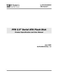
GOOD RF thermal relief<br />
Figure 3 - Example of a GOOD RF Thermal Relief<br />
4.6.1.3. Antenna and RF Signal Trace<br />
The PCB trace that feeds the RF output port must be designed for a 50 ohm characteristic<br />
impedance, coplanar, or routed into internal layers to keep the top layer continuous around<br />
and underneath the <strong>Enabler</strong> module. Ample ground vias should be provided around the RF<br />
contacts, the RF trace and launch pad. If possible, keep I/O and power traces away from the<br />
RF port. This includes traces running parallel or orthogonal to it. Thermal relief should not<br />
be used on the antenna output port ground pads. The designer must pay close attention to<br />
the size of the pad and thickness of the dielectric beneath the signal pad and trace. Most<br />
PCB manufacturers can adjust the trace width to maintain 50 ohms impedance if the traces<br />
are identified and instructions are included on the FAB drawing. This service is typically<br />
provided at no or minimal additional cost.<br />
For minimum RF emissions due to the fundamental frequency of operation, the <strong>Enabler</strong><br />
module works best with an antenna load that has a VSWR of 1.5:1 or better. The antenna<br />
should not have gain at the harmonic frequencies, otherwise, the conducted harmonics could<br />
get amplified to a point where the product no longer passes type approval. However, for<br />
applications where antenna quality is less than ideal, it is recommended to have a low pass<br />
filter (Pi structure with N=3) in the RF path to the antenna. This is a secondary plan should<br />
there be a need to lower harmonic levels at frequencies above the PCS band. The pad<br />
structure may also be used to match the antenna load impedance, if required. If it is not<br />
needed, a capacitor of low reactance may be used to bridge the Pi structure.<br />
The RF cable going between the Enable module and the antenna is very lossy, therefore, the<br />
length of this cable should be kept as short a possible.<br />
GSM0308PB001 16 Version 1.03– 7/17/2007