Enabler II-G Assiste GPS Integration Guide - Farnell
Enabler II-G Assiste GPS Integration Guide - Farnell
Enabler II-G Assiste GPS Integration Guide - Farnell
You also want an ePaper? Increase the reach of your titles
YUMPU automatically turns print PDFs into web optimized ePapers that Google loves.
Enfora <strong>Enabler</strong> <strong>II</strong>I-G<br />
Modem <strong>Integration</strong> <strong>Guide</strong><br />
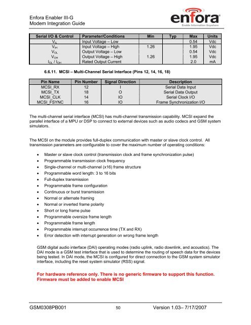
Serial I/O & Control Parameter/Conditions Min Typ Max Units<br />
VIL Input Voltage – Low 0.54 Vdc<br />
VIH Input Voltage – High 1.26 1.95 Vdc<br />
VOL Output Voltage – Low 0.54 Vdc<br />
VOH Output Voltage – High 1.26 1.95 Vdc<br />
IOL / IOH Rated Output Current 2.0 mA<br />
6.6.11. MCSI – Multi-Channel Serial Interface (Pins 12, 14, 16, 18)<br />
Pin Name Pin Number Signal Direction Description<br />
MCSI_RX 12 I Serial Data Input<br />
MCSI_TX 18 O Serial Data Output<br />
MCSI_CLK 14 IO Serial Clock I/O<br />
MCSI_FSYNC 16 IO Frame Synchronization I/O<br />
The multi-channel serial interface (MCSI) has multi-channel transmission capability. MCSI expand the<br />
parallel interface of a MPU or DSP to connect to external devices such as audio codecs and GSM system<br />
simulators.<br />
The MCSI on the module provides full-duplex communication with master or slave clock control. All<br />
transmission parameters are configurable to cover the maximum number of operating conditions:<br />
• Master or slave clock control (transmission clock and frame synchronization pulse)<br />
• Programmable transmission clock frequency<br />
• Single-channel or multi-channel (x16) frame structure<br />
• Programmable word length: 3 to 16 bits<br />
• Full-duplex transmission<br />
• Programmable frame configuration<br />
• Continuous or burst transmission<br />
• Normal or alternate framing<br />
• Normal or inverted frame polarity<br />
• Short or long frame pulse<br />
• Programmable oversize frame length<br />
• Programmable frame length<br />
• Programmable interrupt occurrence time (TX and RX)<br />
• Error detection with interrupt generation on wrong frame length<br />
GSM digital audio interface (DAI) operating modes (radio uplink, radio downlink, and acoustics). The<br />
DAI mode is a GSM test interface that is used to determine the routing of speech data for the devices<br />
being tested. In DAI mode, the MCSI is configured for direct connection to the GSM system simulator<br />
interface, including the reset system simulator (RSS) signal.<br />
For hardware reference only. There is no generic firmware to support this function.<br />
Firmware must be added to enable MCSI<br />
GSM0308PB001 50 Version 1.03– 7/17/2007


