Onsite Use of Recycled Asphalt Pavement Materials and Geocells to ...
Onsite Use of Recycled Asphalt Pavement Materials and Geocells to ...
Onsite Use of Recycled Asphalt Pavement Materials and Geocells to ...
You also want an ePaper? Increase the reach of your titles
YUMPU automatically turns print PDFs into web optimized ePapers that Google loves.
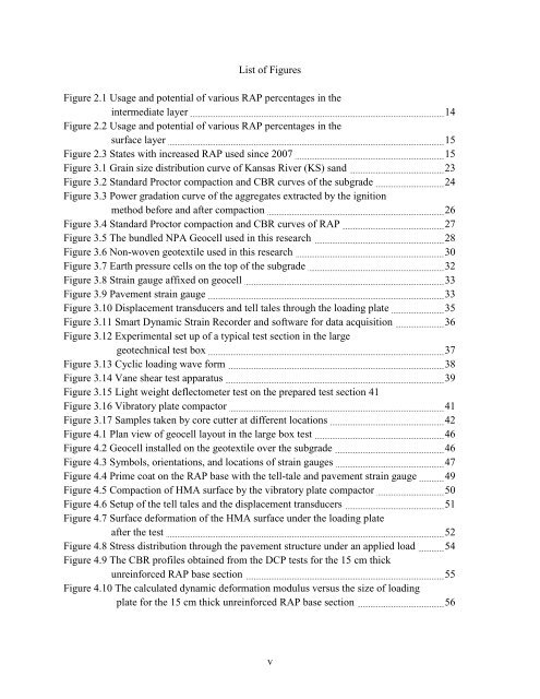
List <strong>of</strong> Figures<br />
Figure 2.1 Usage <strong>and</strong> potential <strong>of</strong> various RAP percentages in the<br />
intermediate layer 14<br />
Figure 2.2 Usage <strong>and</strong> potential <strong>of</strong> various RAP percentages in the<br />
surface layer 15<br />
Figure 2.3 States with increased RAP used since 2007 15<br />
Figure 3.1 Grain size distribution curve <strong>of</strong> Kansas River (KS) s<strong>and</strong> 23<br />
Figure 3.2 St<strong>and</strong>ard Proc<strong>to</strong>r compaction <strong>and</strong> CBR curves <strong>of</strong> the subgrade 24<br />
Figure 3.3 Power gradation curve <strong>of</strong> the aggregates extracted by the ignition<br />
method before <strong>and</strong> after compaction 26<br />
Figure 3.4 St<strong>and</strong>ard Proc<strong>to</strong>r compaction <strong>and</strong> CBR curves <strong>of</strong> RAP 27<br />
Figure 3.5 The bundled NPA Geocell used in this research 28<br />
Figure 3.6 Non-woven geotextile used in this research 30<br />
Figure 3.7 Earth pressure cells on the <strong>to</strong>p <strong>of</strong> the subgrade 32<br />
Figure 3.8 Strain gauge affixed on geocell 33<br />
Figure 3.9 <strong>Pavement</strong> strain gauge 33<br />
Figure 3.10 Displacement transducers <strong>and</strong> tell tales through the loading plate 35<br />
Figure 3.11 Smart Dynamic Strain Recorder <strong>and</strong> s<strong>of</strong>tware for data acquisition 36<br />
Figure 3.12 Experimental set up <strong>of</strong> a typical test section in the large<br />
geotechnical test box 37<br />
Figure 3.13 Cyclic loading wave form 38<br />
Figure 3.14 Vane shear test apparatus 39<br />
Figure 3.15 Light weight deflec<strong>to</strong>meter test on the prepared test section 41<br />
Figure 3.16 Vibra<strong>to</strong>ry plate compac<strong>to</strong>r 41<br />
Figure 3.17 Samples taken by core cutter at different locations 42<br />
Figure 4.1 Plan view <strong>of</strong> geocell layout in the large box test 46<br />
Figure 4.2 Geocell installed on the geotextile over the subgrade 46<br />
Figure 4.3 Symbols, orientations, <strong>and</strong> locations <strong>of</strong> strain gauges 47<br />
Figure 4.4 Prime coat on the RAP base with the tell-tale <strong>and</strong> pavement strain gauge 49<br />
Figure 4.5 Compaction <strong>of</strong> HMA surface by the vibra<strong>to</strong>ry plate compac<strong>to</strong>r 50<br />
Figure 4.6 Setup <strong>of</strong> the tell tales <strong>and</strong> the displacement transducers 51<br />
Figure 4.7 Surface deformation <strong>of</strong> the HMA surface under the loading plate<br />
after the test 52<br />
Figure 4.8 Stress distribution through the pavement structure under an applied load 54<br />
Figure 4.9 The CBR pr<strong>of</strong>iles obtained from the DCP tests for the 15 cm thick<br />
unreinforced RAP base section 55<br />
Figure 4.10 The calculated dynamic deformation modulus versus the size <strong>of</strong> loading<br />
plate for the 15 cm thick unreinforced RAP base section 56<br />
v


