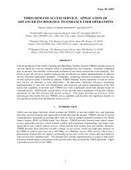
Operational Interface Procedures for the South Pole TDRSS Relay ...
Operational Interface Procedures for the South Pole TDRSS Relay ...
Operational Interface Procedures for the South Pole TDRSS Relay ...

Create successful ePaper yourself
Turn your PDF publications into a flip-book with our unique Google optimized e-Paper software.
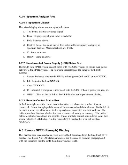
A.2.6 Spectrum Analyzer Area<br />
A.2.6.1 Spectrum Display<br />
This visual display shows various signal selections.<br />
a. Test Point: Displays selected signal<br />
b. Peak: Displays signal peak in MHz and dBm<br />
c. Poll: Same as above.<br />
d. Control box of test point menu: Can select different signals to display in<br />
spectrum display. Menu selections are TBD.<br />
e. C: Same as above.<br />
f. OPEN: Same as above.<br />
A.2.7 Uninterrupted Power Supply (UPS) Status Box<br />
The <strong>South</strong> <strong>Pole</strong> SPTR system is configured with two UPS systems to ensure even power<br />
delivery to <strong>the</strong> SPTR system. The following indicators are <strong>the</strong> same <strong>for</strong> both UPS<br />
systems.<br />
a. Status: Indicates whe<strong>the</strong>r <strong>the</strong> UPS is online (green On Line lit) or not (XXXX).<br />
b. Ld: Indicates <strong>the</strong> load XXXXX<br />
c. Cap: XXXXXX<br />
d. C: Indicated if computer is interfaced with <strong>the</strong> UPS. If box is green, yes; red, no.<br />
e. OPEN: Click on this to link to <strong>the</strong> UPS detailed status parameters display.<br />
A.2.3 Remote Control Status Box<br />
In <strong>the</strong> lower right area, <strong>the</strong> connection in<strong>for</strong>mation box shows <strong>the</strong> number of users<br />
connected. Below is displayed <strong>the</strong> name of <strong>the</strong> connected and <strong>the</strong>ir address. To <strong>the</strong> left of<br />
this area a scroll box allows user to dial up each user connected and <strong>the</strong>ir address. The<br />
bottom blue box displays whe<strong>the</strong>r <strong>the</strong> user is connected locally or remotely. The button<br />
below toggles between local and remote. If user wants to control system from local, <strong>the</strong>n<br />
should select LOCAL button. On <strong>the</strong> remote SPTR display this area will display,<br />
“LOCAL”.<br />
A.3 Remote SPTR (Remsptr) Display<br />
This display page is colored aqua green to visually differentiate from <strong>the</strong> blue local SPTR<br />
display. See figure A-2. All status parameters are <strong>the</strong> same as found in paragraph A.2<br />
with <strong>the</strong> exception that <strong>the</strong> GMT box displays actual GMT.<br />
a2302apa A-5 532-OIP-NCC-SPTR