think-cell technical report TC2003/01 A GUI-based Interaction ...
think-cell technical report TC2003/01 A GUI-based Interaction ...
think-cell technical report TC2003/01 A GUI-based Interaction ...
You also want an ePaper? Increase the reach of your titles
YUMPU automatically turns print PDFs into web optimized ePapers that Google loves.
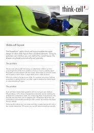
4.3 Specifying the User Interface INTERACTION CONCEPT<br />
1. In addition to Power-<br />
Point AutoShapes, “smart elements”<br />
can be inserted from the<br />
<strong>think</strong>-<strong>cell</strong> menu.<br />
Single-Click Insertion<br />
2a. In insertion mode,<br />
when the mouse cursor is moved, the<br />
software proposes reasonable placements<br />
for the new element.<br />
2b. Alternatively, an arbitrary<br />
area can be selected by drag-and-drop.<br />
Borders are snapped to existing gridlines,<br />
if close enough.<br />
Figure 16: Inserting a new shape into the smart grid<br />
3. New gridlines are<br />
generated, if required.<br />
4. Layout optimization:<br />
Shapes are sized appropriately,<br />
the layout is centered, etc.<br />
The single-click insertion is strictly optimized to make the common case fast. The<br />
idea is to detect common cases <strong>based</strong> on the mouse pointer position and existing<br />
shapes on the slide. The most typical insertion location that is detected by my<br />
software is shown to the user by a transparent rectangle that serves as a placeholder<br />
for the new element. If the user is satisfied with the system’s proposition, a single<br />
click suffices to insert the new element.<br />
This concept is enabled by the smart grid and the solver. In plain PowerPoint,<br />
it would be pointless to suggest one pixel position or another. However, with the<br />
solver taking care of the details, the space of distinct solutions for placement is<br />
drastically reduced: Each edge of the new element’s bounding box can either be<br />
bound to an existing gridline, or it creates a new gridline between two existing ones.<br />
As long as all edges that share the same position are bound to the same gridline and<br />
the total order of gridlines is preserved, the absolute placement in terms of pixels<br />
does not make a difference. The solver would fix it, anyway.<br />
Figures 17 through 20 show the effect of some heuristics that propose common<br />
placements. All figures are live screenshots from my prototypical implementation<br />
that is presented in chapter 5.<br />
The proposed placement is <strong>based</strong> on the dimensions of the nearest shapes that<br />
are found in the horizontal and vertical projection of the mouse pointer position.<br />
When no shapes are found, some arbitrary default size is proposed, centered around<br />
the mouse pointer (Fig. 17(a)). On the other hand, if some shape is found and the<br />
mouse pointer is sufficiently close to that shape, the new element is placed flush<br />
next to it, taking on the same height or width, respectively (Fig. 17(b)). If in both<br />
53


