think-cell technical report TC2003/01 A GUI-based Interaction ...
think-cell technical report TC2003/01 A GUI-based Interaction ...
think-cell technical report TC2003/01 A GUI-based Interaction ...

You also want an ePaper? Increase the reach of your titles
YUMPU automatically turns print PDFs into web optimized ePapers that Google loves.
4.3 Specifying the User Interface INTERACTION CONCEPT<br />
free drag<br />
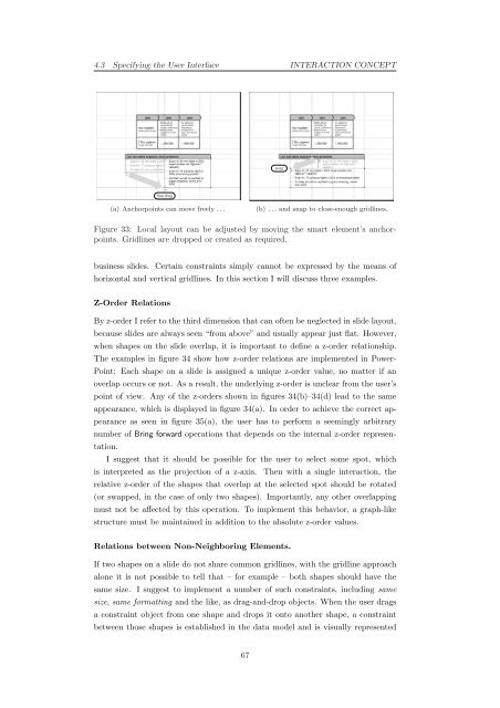
(a) Anchorpoints can move freely . . .<br />
snap<br />
(b) . . . and snap to close-enough gridlines.<br />
Figure 33: Local layout can be adjusted by moving the smart element’s anchorpoints.<br />
Gridlines are dropped or created as required.<br />
business slides. Certain constraints simply cannot be expressed by the means of<br />
horizontal and vertical gridlines. In this section I will discuss three examples.<br />
Z-Order Relations<br />
By z-order I refer to the third dimension that can often be neglected in slide layout,<br />
because slides are always seen “from above” and usually appear just flat. However,<br />
when shapes on the slide overlap, it is important to define a z-order relationship.<br />
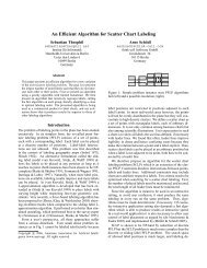
The examples in figure 34 show how z-order relations are implemented in Power-<br />
Point: Each shape on a slide is assigned a unique z-order value, no matter if an<br />
overlap occurs or not. As a result, the underlying z-order is unclear from the user’s<br />
point of view. Any of the z-orders shown in figures 34(b)–34(d) lead to the same<br />
appearance, which is displayed in figure 34(a). In order to achieve the correct ap-<br />
pearance as seen in figure 35(a), the user has to perform a seemingly arbitrary<br />
number of Bring forward operations that depends on the internal z-order represen-<br />
tation.<br />
I suggest that it should be possible for the user to select some spot, which<br />
is interpreted as the projection of a z-axis. Then with a single interaction, the<br />
relative z-order of the shapes that overlap at the selected spot should be rotated<br />
(or swapped, in the case of only two shapes). Importantly, any other overlapping<br />
must not be affected by this operation. To implement this behavior, a graph-like<br />
structure must be maintained in addition to the absolute z-order values.<br />
Relations between Non-Neighboring Elements.<br />
If two shapes on a slide do not share common gridlines, with the gridline approach<br />
alone it is not possible to tell that – for example – both shapes should have the<br />
same size. I suggest to implement a number of such constraints, including same<br />
size, same formatting and the like, as drag-and-drop objects. When the user drags<br />
a constraint object from one shape and drops it onto another shape, a constraint<br />
between those shapes is established in the data model and is visually represented<br />
67