Automotive spark-ignited direct-injection gasoline engines
Automotive spark-ignited direct-injection gasoline engines
Automotive spark-ignited direct-injection gasoline engines

Create successful ePaper yourself
Turn your PDF publications into a flip-book with our unique Google optimized e-Paper software.
F. Zhao et al. / Progress in Energy and Combustion Science 25 (1999) 437–562 539<br />
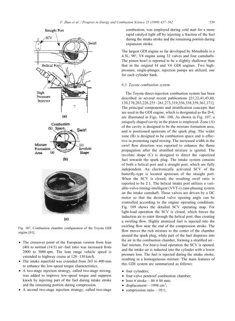
Fig. 107. Combustion chamber configuration of the Toyota GDI<br />
engine [41].<br />
• The crossover point of the European version from lean<br />
(40) to normal (14.5) air–fuel ratio was increased from<br />
2000 to 3000 rpm. The lean range vehicle speed is<br />
extended to highway cruise at 120–130 km/h.<br />
• The intake manifold was extended from 265 to 400 mm<br />
to enhance the low-speed torque characteristics.<br />
• A two-stage <strong>injection</strong> strategy, called two-stage mixing,<br />
was added to improve low-speed torque and suppress<br />
knock by injecting part of the fuel during intake stroke<br />
and the remaining portion during compression.<br />
• A second two-stage <strong>injection</strong> strategy, called two-stage<br />
combustion, was employed during cold start for a more<br />
rapid catalyst light off by injecting a fraction of the fuel<br />
during the intake stroke and the remaining portion during<br />
expansion stroke.<br />
The largest GDI engine so far developed by Mitsubishi is a<br />
4.5L, 90, V8 engine using 32 valves and four camshafts.<br />
The piston bowl is reported to be a slightly shallower than<br />
that in the original I4 and V6 GDI <strong>engines</strong>. Two highpressure,<br />
single-plunger, <strong>injection</strong> pumps are utilized, one<br />
for each cylinder bank.<br />
6.3. Toyota combustion system<br />
The Toyota <strong>direct</strong>-<strong>injection</strong> combustion system has been<br />
described in several recent publications [21,22,41,43,60,<br />
139,170,203,226,255–261,273,319,356,358,359,361,371].<br />
The principal components and stratification concepts that<br />
are used in the GDI engine, which is designated as the D-4,<br />
are illustrated in Figs. 106–108. As shown in Fig. 107, a<br />
uniquely shaped cavity in the piston is employed. Zone (A)<br />
of the cavity is designed to be the mixture formation area,<br />
and is positioned upstream of the <strong>spark</strong> plug. The wider<br />
zone (B) is designed to be combustion space and is effective<br />
in promoting rapid mixing. The increased width in the<br />
swirl flow <strong>direct</strong>ion was reported to enhance the flame<br />
propagation after the stratified mixture is <strong>ignited</strong>. The<br />
involute shape (C) is designed to <strong>direct</strong> the vaporized<br />
fuel towards the <strong>spark</strong> plug. The intake system consists<br />
of both a helical port and a straight port, which are fully<br />
independent. An electronically activated SCV of the<br />
butterfly-type is located upstream of the straight port.<br />
When the SCV is closed, the resulting swirl ratio is<br />
reported to be 2.1. The helical intake port utilizes a variable-valve-timing-intelligent<br />
(VVT-i) cam-phasing system<br />
on the intake camshaft. These valves are driven by a DC<br />
motor so that the desired valve opening angle can be<br />
controlled according to the engine operating conditions.<br />
Fig. 109 shows the detailed SCV operating map. For<br />
light-load operation the SCV is closed, which forces the<br />
induction air to enter through the helical port, thus creating<br />
a swirling flow. Highly atomized fuel is injected into the<br />
swirling flow near the end of the compression stroke. The<br />
flow moves the rich mixture to the center of the chamber<br />
around the <strong>spark</strong> plug, while part of the fuel disperses into<br />
the air in the combustion chamber, forming a stratified air–<br />
fuel mixture. For heavy-load operation the SCV is opened,<br />
and the intake air is inducted into the cylinder with a lower<br />
pressure loss. The fuel is injected during the intake stroke,<br />
resulting in a homogeneous mixture. The main features of<br />
this GDI system are summarized as follows:<br />
• four cylinders;<br />
• four-valve pentroof combustion chamber;<br />
• bore × stroke—86 × 86 mm;<br />
• displacement—1998 cm 3 ;<br />
• compression ratio—10:1;