Automotive spark-ignited direct-injection gasoline engines
Automotive spark-ignited direct-injection gasoline engines
Automotive spark-ignited direct-injection gasoline engines

Create successful ePaper yourself
Turn your PDF publications into a flip-book with our unique Google optimized e-Paper software.
468<br />
F. Zhao et al. / Progress in Energy and Combustion Science 25 (1999) 437–562<br />
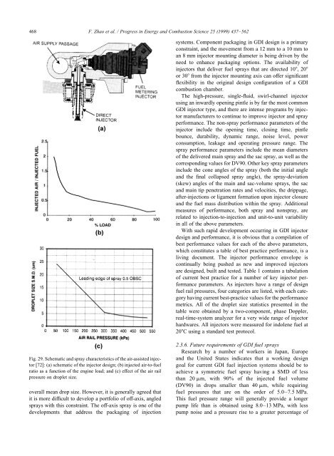
Fig. 29. Schematic and spray characteristics of the air-assisted injector<br />
[72]: (a) schematic of the injector design; (b) injected air-to-fuel<br />
ratio as a function of the engine load; and (c) effect of the air rail<br />
pressure on droplet size.<br />
overall mean drop size. However, it is generally agreed that<br />
it is more difficult to develop a portfolio of off-axis, angled<br />
sprays with this constraint. The off-axis spray is one of the<br />
developments that address the packaging of <strong>injection</strong><br />
systems. Component packaging in GDI design is a primary<br />
constraint, and the movement from a 12 mm to a 10 mm to<br />
an 8 mm injector mounting diameter is being driven by the<br />
need to enhance packaging options. The availability of<br />
injectors that deliver fuel sprays that are <strong>direct</strong>ed 10, 20<br />
or 30 from the injector mounting axis can offer significant<br />
flexibility in the original design configuration of a GDI<br />
combustion chamber.<br />
The high-pressure, single-fluid, swirl-channel injector<br />
using an inwardly opening pintle is by far the most common<br />
GDI injector type, and there are intense programs by injector<br />
manufacturers to continue to improve injector and spray<br />
performance. The non-spray performance parameters of the<br />
injector include the opening time, closing time, pintle<br />
bounce, durability, dynamic range, noise level, power<br />
consumption, leakage and operating pressure range. The<br />
spray performance parameters include the mean diameters<br />
of the delivered main spray and the sac spray, as well as the<br />
corresponding values for DV90. Other key spray parameters<br />
include the cone angles of the spray (both the initial angle<br />
and the final collapsed spray angle), the spray-deviation<br />
(skew) angles of the main and sac-volume sprays, the sac<br />
and main tip penetration rates and velocities, the drippage,<br />
after-<strong>injection</strong>s or ligament formation upon injector closure<br />
and the fuel mass distribution within the spray. Additional<br />
measures of performance, both spray and nonspray, are<br />
related to <strong>injection</strong>-to-<strong>injection</strong> and unit-to-unit variability<br />
in all of the above parameters.<br />
With such rapid development occurring in GDI injector<br />
design and performance, it is obvious that a compilation of<br />
best performance values for each of the above parameters,<br />
which constitutes a table of best practice performance, is a<br />
living document. The injector performance envelope is<br />
continually being pushed as new and improved injectors<br />
are designed, built and tested. Table 1 contains a tabulation<br />
of current best practice for a number of key injector performance<br />
parameters. As injectors have a range of design<br />
fuel rail pressures, four categories are listed, with each category<br />
having current best-practice values for the performance<br />
metrics. All of the droplet size statistics presented in the<br />
table were obtained by a two-component, phase Doppler,<br />
real-time-system analyzer for a very wide range of injector<br />
hardwares. All injectors were measured for indolene fuel at<br />
20C using a standard test protocol.<br />
2.3.6. Future requirements of GDI fuel sprays<br />
Research by a number of workers in Japan, Europe<br />
and the United States indicates that a working design<br />
goal for current GDI fuel <strong>injection</strong> systems should be to<br />
achieve a symmetric fuel spray having a SMD of less<br />
than 20 mm, with 90% of the injected fuel volume<br />
(DV90) in drops smaller than 40 mm, while requiring<br />
fuel pressures that are on the order of 5.0–7.5 MPa.<br />
This fuel pressure range will generally provide a longer<br />
pump life than is obtained using 8.0–13 MPa, with less<br />
pump noise and a pressure rise to a greater percentage of