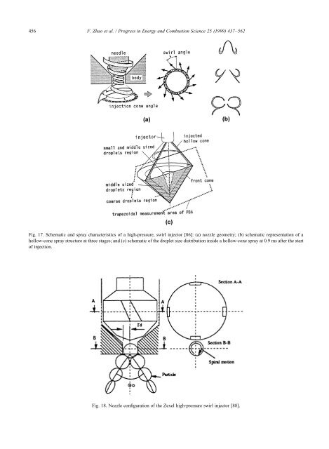
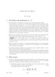
456 F. Zhao et al. / Progress in Energy and Combustion Science 25 (1999) 437–562 Fig. 17. Schematic and spray characteristics of a high-pressure, swirl injector [86]: (a) nozzle geometry; (b) schematic representation of a hollow-cone spray structure at three stages; and (c) schematic of the droplet size distribution inside a hollow-cone spray at 0.9 ms after the start of <strong>injection</strong>. Fig. 18. Nozzle configuration of the Zexel high-pressure swirl injector [88].
F. Zhao et al. / Progress in Energy and Combustion Science 25 (1999) 437–562 457 injector, the spray cone angle generally decreases with an increase in ambient gas density until a minimum angle is reached. The ambient gas density also has a strong influence on the minimum atomization level produced by pressure-swirl atomizers. Fraidl et al. [82] reported measurements verifying that ambient pressure has a greater effect on the spray cone angle than does the fuel <strong>injection</strong> pressure. With nonswirl atomizers, however, an increase in ambient gas density generally yields a wider spray cone angle. This results from an increased aerodynamic drag on the droplets, which produces a greater deceleration in the axial <strong>direct</strong>ion than in the radial <strong>direct</strong>ion. Under conditions of higher incylinder air density, corresponding to late <strong>injection</strong> at part load, a more compact droplet plume is required for a higher degree of stratification. This would imply that the high-pressure swirl injector might be more applicable to GDI late<strong>injection</strong> applications. The spray structure of an AlliedSignal high-pressure swirl injector which utilizes a fuel <strong>injection</strong> pressure of 6.9 MPa was characterized by Evers [83]. This injector design is shown schematically in Fig. 16. Four regions denoted as leading-edge, cone, trailing-edge, and vortex-cloud, were identified for the hollow-cone spray that is produced. The leading-edge region was found to show the largest droplet size due to the low fuel velocity at the beginning of the fuel <strong>injection</strong> pulse. After the pintle is opened fully, the fuel attains a steady velocity and a conical region of small droplets is formed. The trailing-edge region is produced as the pintle closes, whereas the vortex-cloud region is formed by the circulating air that carries small droplets from the spray. As the <strong>injection</strong> pulse ends, the vortex-cloud region continues to grow. An increase in the ambient pressure results in an increase in the droplet size within the spray region, and an increase in the level of swirl of the fuel leaving the fuel injector yields an increase in the mean droplet size in the leading-edge and cone regions of the spray. The droplet size of the vortex-cloud region is not significantly influenced by the fuel swirl number. This was theorized to result from the fact that the size of the droplets entrained into the vortex cloud is determined by the ambient air properties. As the ambient air density is increased, the droplet size in the vortex cloud region also increases due to changes in the entrainment characteristics of the ambient air. The droplet size in the vortex cloud is not changed when the fuel <strong>injection</strong> pressure is increased, as the ambient air properties are not altered. The detailed structure of sprays from Siemens high-pressure fuel injectors was studied by Zhao et al. [84,85] using laser-light sheet photography and phase Doppler techniques. A toroidal vortex was observed late in the <strong>injection</strong> event at reduced <strong>injection</strong> pressures or short <strong>injection</strong> durations. The circumferential distribution of the spray was found to be fairly irregular. The spray tip penetration and the spray cone angle were found to decrease monotonically with an increase in the ambient pressure. The characteristics of hollow-cone sprays generated by a high-pressure swirl injector with an exit-angle of 70C were predicted using the generalized tank-and-tube (GTT) code with an included spray model, and were validated using PDA measurements by Yamauchi and Wakisaka [86] and Yamauchi et al. [87]. The schematic representation of the injector nozzle geometry is illustrated in Fig. 17(a). The predictions were for a swirl angle of 40 and an initial droplet velocity of 60 m/s to simulate a spray injected at 7.0 MPa into air at 1 atm. The schematic representation of the hollow-cone spray structure derived from the calculation is shown in Fig. 17(b). The transient spray development was classified into three time regimes. During the first stage of spray formation, the droplets form a hollow cone. In the second stage, the spray structure changes as the laterinjected droplets move towards the previously injected droplets, which are slowed due to drag. A toroidal vortex is formed around the lower part of the cone and appears as two counter-rotating vortices in the vertical cross section. In the third and final stage, the spray structure attains a steadystate condition, and the entire spray grows and moves away from the injector tip. The interaction between the droplets and the gas flow were found to vary with the detailed spray structure, and was found to be more pronounced for smaller droplets. It is interesting to note that for the case corresponding to a monodisperse spray of 40 mm droplets, the droplets do not form a torus. For the sprays with different droplet size distributions but the same fuel flow rates, the spray structures are considerably different. It was also found that the fuel swirl component plays an important role in the spray development. The spray shapes at the transition between cone growth and torus formation are quite different with and without fuel swirl. The spray cone-angle for the case with swirl was found to be significantly larger than that for the nonswirl case [330]. However, the spray-penetration characteristics for the swirl and nonswirl cases were found to be similar, which is somewhat surprising. As expected, the mean droplet size at the spray tip was found to increase with an increase in the ambient gas pressure due to the influence of the coalescence. As is schematically illustrated in Fig. 17(c), droplets in the mid-size range are found inside the coarse droplet region while droplets smaller than 10 mm do not form a hollow cone and are observed to concentrate towards the injector axis. At 0.4 ms after the start of <strong>injection</strong>, all droplets near the injector tip were found to concentrate in a small region near the injector axis, verifying that the cone angle at the start of fuel <strong>injection</strong> is very small. At 0.6 ms after the initiation of <strong>injection</strong>, it was found that droplets near the injector tip are concentrated in an angular ring, indicating a wider cone angle. The instantaneous spray cone angle was found to increase from nearly zero to the steady value in proportion to the needle opening time. The measured droplet number density after the end of fuel <strong>injection</strong> confirmed that apparent vortex formation occurs only for droplets in the range of 10–25 mm, not for other droplet diameter ranges. Moreover, the total number of droplets in the diameter range