Automotive spark-ignited direct-injection gasoline engines
Automotive spark-ignited direct-injection gasoline engines
Automotive spark-ignited direct-injection gasoline engines

Create successful ePaper yourself
Turn your PDF publications into a flip-book with our unique Google optimized e-Paper software.
510<br />
F. Zhao et al. / Progress in Energy and Combustion Science 25 (1999) 437–562<br />
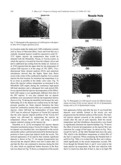
Fig. 77. Photograph of the appearance of a GDI injector with deposits<br />
after 30 h of engine operation [214].<br />
at a location under the intake port. GDI combustion systems<br />
such as those of Mercedes-Benz, Isuzu and Ford that use a<br />
centrally mounted injector would be expected to yield 10–<br />
15C higher injector tip temperatures than would be<br />
obtained with the Mitsubishi, Nissan, or Toyota system, in<br />
which the injector is located far from the exhaust valves and<br />
derive additional tip cooling from the intake air. Jackson et<br />
al. [195] reported that the upper limit for tip temperature of<br />
current GDI injectors is in the range of 150–200C. Twodimensional<br />
finite element analysis (FEA) and analytical<br />
calculations showed that the higher flame heat fluxes<br />
occur at the center of the combustion chamber. For a central<br />
injector the best location for minimum tip temperature is to<br />
be as close as possible to the intake valve seats. Fig. 76<br />
shows the injector surface temperature as measured in the<br />
Mitsubishi GDI engine during the continuous high-speed<br />
full-load operation and a subsequent hot soak period [50].<br />
It was reported that the injector tip temperature of the Mitsubishi<br />
GDI engine is not significantly different from that of<br />
the PFI injector. It was also claimed that no deposit<br />
problems were encountered with the tip temperature history<br />
shown in Fig. 76 during the durability test because the soot,<br />
lubricating oil or the deposit are washed away by the highpressure<br />
<strong>gasoline</strong> jet. Some deposit formation has been<br />
noted for combustion systems that use a centrally mounted<br />
injector, where full-load tip temperatures of more than<br />
150C may be achieved. Engineers at Toyota [41] reported<br />
that the early injector deposit problem of the Toyota D-4<br />
engine was alleviated by maintaining the injector tip<br />
temperature always below 150C, and using a special<br />
organic material coating on the injector tip.<br />
Kinoshita et al. [214] investigated the injector deposit<br />
formation mechanism using a Toyota D-4 engine. The injector<br />
deposit was classified into: soot deposited on the nozzle<br />
and needle surface; and fuel polymerized by thermal decomposition<br />
to form a gum-type deposit inside the nozzle. The<br />
outward appearance of an injector that contains significant<br />
deposits is shown in Fig. 77. An engine dynamometer test<br />
showed that the deposit effects were first evident after 2 h<br />
and that the flow rate continued to decrease during the first<br />
8 h, after which no significant further decrease in the flow<br />
rate was observed. Fig. 78 shows a comparison of the nozzle<br />
Fig. 78. Photographs of a GDI injector nozzle for different dynamometer<br />
test hours [214]: (a) new injector; (b) 4 h of dynamometer<br />
testing; and (c) 8 h of dynamometer testing.<br />
hole appearance before and after the test. It was found that<br />
deposits were initially formed at the nozzle exit and<br />
progressed into the internal surfaces of the nozzle. The internal<br />
injector deposit occurred at the position where fuel<br />
resides after the end of each <strong>injection</strong>. Both the nozzle<br />
temperature and fuel distillation characteristics were found<br />
to significantly dominate the deposit buildup. Fig. 79 shows<br />
the effect of nozzle tip temperature on the injector flow rate<br />
reduction for a range of fuel types. As shown in Fig. 79(a),<br />
except for fuel E, all the other blended fuels have the same<br />
T90, which is the distillation temperature at which 90% of<br />
the fuel is vaporized. When comparing the blended fuels A<br />
and D in Fig. 79(b), it is evident that the flow rate is diminished<br />
significantly as the nozzle temperature exceeds T90.<br />
Even though the blended fuels A and E were tested at the<br />
same injector tip temperature, the flow rate reduction with<br />
fuel E is much less than that of fuel A, due to its high T90