Automotive spark-ignited direct-injection gasoline engines
Automotive spark-ignited direct-injection gasoline engines
Automotive spark-ignited direct-injection gasoline engines

Create successful ePaper yourself
Turn your PDF publications into a flip-book with our unique Google optimized e-Paper software.
488<br />
F. Zhao et al. / Progress in Energy and Combustion Science 25 (1999) 437–562<br />
Fig. 48. Valve size limitation for optional injector and <strong>spark</strong> plug locations [57].<br />
this configuration avoids <strong>spark</strong> plug wetting during early<br />
<strong>injection</strong> by taking advantage of the intake charge motion.<br />
However, there was no mention as to how the higher thermal<br />
loading on the exhaust side could negatively affect the injector<br />
deposit buildup. Another configuration was investigated<br />
that had the injector and <strong>spark</strong> plug mounted longitudinally,<br />
namely in line with the crankshaft in order to avoid the<br />
adverse effect of air motion on transporting the fuel to the<br />
<strong>spark</strong> plug in a wall-guided system. An air-guided system<br />
was also discussed for this geometry, which was reported to<br />
require an injector location that was offset towards the<br />
exhaust side. A central piston bowl was used for optimizing<br />
the wall-guided system, whereas a piston bowl offset toward<br />
the exhaust side was used for optimizing the air-guided<br />
system. It was reported that the central injector engine, in<br />
a wall-guided configuration, produces the highest UBHC<br />
emissions among all the concepts evaluated; and that the<br />
MBT combustion phasing is far more advanced. Lake et<br />
al. [185] reported that the central <strong>spark</strong> plug and injector<br />
configuration is not common, but that it does provide a long<br />
spray path before wall impingement. It was found to yield<br />
excellent homogeneous operation with good EGR tolerance<br />
at part load and good air utilization at full load. It was<br />
claimed that this configuration can be successfully packaged<br />
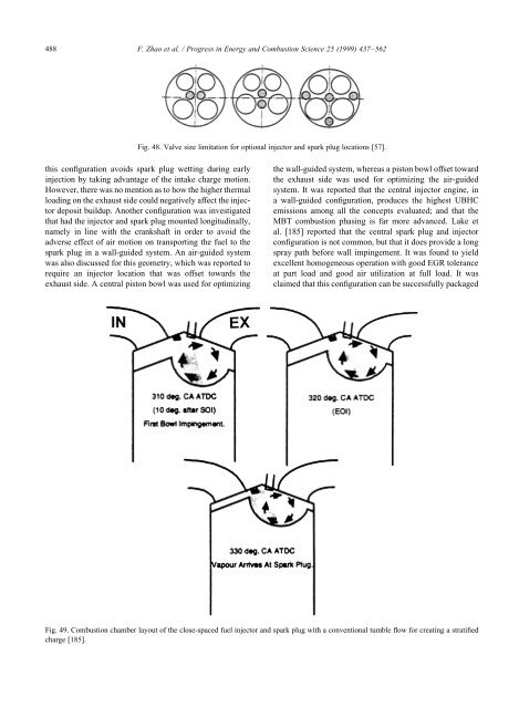
Fig. 49. Combustion chamber layout of the close-spaced fuel injector and <strong>spark</strong> plug with a conventional tumble flow for creating a stratified<br />
charge [185].