Automotive spark-ignited direct-injection gasoline engines
Automotive spark-ignited direct-injection gasoline engines
Automotive spark-ignited direct-injection gasoline engines

You also want an ePaper? Increase the reach of your titles
YUMPU automatically turns print PDFs into web optimized ePapers that Google loves.
F. Zhao et al. / Progress in Energy and Combustion Science 25 (1999) 437–562 535<br />
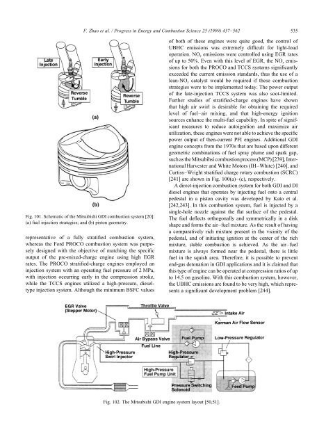
Fig. 101. Schematic of the Mitsubishi GDI combustion system [20]:<br />
(a) fuel <strong>injection</strong> strategies; and (b) piston geometry.<br />
representative of a fully stratified combustion system,<br />
whereas the Ford PROCO combustion system was purposely<br />
designed with the objective of matching the specific<br />
output of the pre-mixed-charge engine using high EGR<br />
rates. The PROCO stratified-charge <strong>engines</strong> employed an<br />
<strong>injection</strong> system with an operating fuel pressure of 2 MPa,<br />
with <strong>injection</strong> occurring early in the compression stroke,<br />
while the TCCS <strong>engines</strong> utilized a high-pressure, dieseltype<br />
<strong>injection</strong> system. Although the minimum BSFC values<br />
Fig. 102. The Mitsubishi GDI engine system layout [50,51].<br />
of both of these <strong>engines</strong> were quite good, the control of<br />
UBHC emissions was extremely difficult for light-load<br />
operation. NOx emissions were controlled using EGR rates<br />
of up to 50%. Even with this level of EGR, the NO x emissions<br />
for both the PROCO and TCCS systems significantly<br />
exceeded the current emission standards, thus the use of a<br />
lean-NO x catalyst would be required if these combustion<br />
strategies were to be implemented today. The power output<br />
of the late-<strong>injection</strong> TCCS system was also soot-limited.<br />
Further studies of stratified-charge <strong>engines</strong> have shown<br />
that high air swirl is desirable for obtaining the required<br />
level of fuel–air mixing, and that high-energy ignition<br />
sources enhance the multi-fuel capability. In spite of significant<br />
measures to reduce autoignition and maximize air<br />
utilization, these <strong>engines</strong> were not able to achieve the specific<br />
power output of then-current PFI <strong>engines</strong>. Additional GDI<br />
engine concepts from the 1970s that are based upon different<br />
geometric combinations of fuel spray plume and <strong>spark</strong> gap,<br />
such as the Mitsubihsi combustion process (MCP) [239], International<br />
Harvester and White Motors (IH–White) [240], and<br />
Curtiss–Wright stratified charge rotary combustion (SCRC)<br />
[241] are shown in Fig. 100(a)–(c), respectively.<br />
A <strong>direct</strong>-<strong>injection</strong> combustion system for both GDI and DI<br />
diesel <strong>engines</strong> that operates by injecting fuel onto a central<br />
pedestal in a piston cavity was developed by Kato et al.<br />
[242,243]. In this combustion system, fuel is injected by a<br />
single-hole nozzle against the flat surface of the pedestal.<br />
The fuel deflects orthogonally and symmetrically in a disk<br />
shape and forms the air–fuel mixture. As the result of having<br />
a comparatively rich mixture present in the vicinity of the<br />
pedestal, and of initiating ignition at the center of the rich<br />
mixture, stable combustion is achieved. As the air–fuel<br />
mixture is always formed near the pedestal, there is little<br />
fuel in the squish area. Therefore, it is possible to prevent<br />
end-gas detonation in GDI applications and it is claimed that<br />
this type of engine can be operated at compression ratios of up<br />
to 14.5 on <strong>gasoline</strong>. With this combustion system, however,<br />
the UBHC emissions are found to be very high, which represents<br />
a significant development problem [244].