Automotive spark-ignited direct-injection gasoline engines
Automotive spark-ignited direct-injection gasoline engines
Automotive spark-ignited direct-injection gasoline engines

Create successful ePaper yourself
Turn your PDF publications into a flip-book with our unique Google optimized e-Paper software.
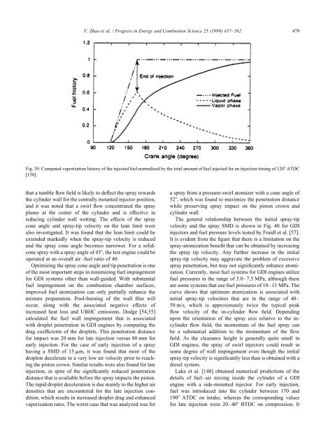
F. Zhao et al. / Progress in Energy and Combustion Science 25 (1999) 437–562 479<br />
Fig. 39. Computed vaporization history of the injected fuel normalized by the total amount of fuel injected for an <strong>injection</strong> timing of 120 ATDC<br />
[158].<br />
that a tumble flow field is likely to deflect the spray towards<br />
the cylinder wall for the centrally mounted injector position,<br />
and it was noted that a swirl flow concentrated the spray<br />
plume at the center of the cylinder and is effective in<br />
reducing cylinder wall wetting. The effects of the spray<br />
cone angle and spray-tip velocity on the lean limit were<br />
also investigated. It was found that the lean limit could be<br />
extended markedly when the spray-tip velocity is reduced<br />
and the spray cone angle becomes narrower. For a solidcone<br />
spray with a spray angle of 45, the test engine could be<br />
operated at an overall air–fuel ratio of 40.<br />
Optimizing the spray cone angle and tip penetration is one<br />
of the most important steps in minimizing fuel impingement<br />
for GDI systems other than wall-guided. With substantial<br />
fuel impingement on the combustion chamber surfaces,<br />
improved fuel atomization can only partially enhance the<br />
mixture preparation. Pool-burning of the wall film will<br />
occur, along with the associated negative effects of<br />
increased heat loss and UBHC emissions. Dodge [54,55]<br />
calculated the fuel wall impingement that is associated<br />
with droplet penetration in GDI <strong>engines</strong> by computing the<br />
drag coefficients of the droplets. This penetration distance<br />
for impact was 20 mm for late <strong>injection</strong> versus 80 mm for<br />
early <strong>injection</strong>. For the case of early <strong>injection</strong> of a spray<br />
having a SMD of 15 mm, it was found that most of the<br />
droplets decelerate to a very low air velocity prior to reaching<br />
the piston crown. Similar results were also found for late<br />
<strong>injection</strong>, in spite of the significantly reduced penetration<br />
distance that is available before the spray impacts the piston.<br />
The rapid droplet deceleration is due mainly to the higher air<br />
densities that are encountered for the late <strong>injection</strong> condition,<br />
which results in increased droplet drag and enhanced<br />
vaporization rates. The worst case that was analyzed was for<br />
a spray from a pressure-swirl atomizer with a cone angle of<br />
52, which was found to maximize the penetration distance<br />
while preserving spray impact on the piston crown and<br />
cylinder wall.<br />
The general relationship between the initial spray-tip<br />
velocity and the spray SMD is shown in Fig. 40 for GDI<br />
injectors and fuel pressure levels tested by Fraidl et al. [57].<br />
It is evident from the figure that there is a limitation on the<br />
spray-atomization benefit that can be obtained by increasing<br />
the spray tip velocity. Any further increase in the initial<br />
spray-tip velocity may aggravate the problem of excessive<br />
spray penetration, but may not significantly enhance atomization.<br />
Currently, most fuel systems for GDI <strong>engines</strong> utilize<br />
fuel pressures in the range of 5.0–7.5 MPa, although there<br />
are some systems that use fuel pressures of 10–13 MPa. The<br />
curve shows that optimum atomization is associated with<br />
initial spray-tip velocities that are in the range of 40–<br />
50 m/s, which is approximately twice the typical peak<br />
flow velocity of the in-cylinder flow field. Depending<br />
upon the orientation of the spray axis relative to the incylinder<br />
flow field, the momentum of the fuel spray can<br />
be a substantial addition to the momentum of the flow<br />
field. As the clearance height is generally quite small in<br />
GDI <strong>engines</strong>, the spray of swirl injectors could result in<br />
some degree of wall impingement even though the initial<br />
spray-tip velocity is significantly less than is obtained with a<br />
diesel system.<br />
Lake et al. [148] obtained numerical predictions of the<br />
details of fuel–air mixing inside the cylinder of a GDI<br />
engine with a side-mounted injector. For early <strong>injection</strong>,<br />
fuel was introduced into the cylinder between 170 and<br />
190 ATDC on intake, whereas the corresponding values<br />
for late <strong>injection</strong> were 20–40 BTDC on compression. It