

PDF (Thesis) - Nottingham eTheses - University of Nottingham
PDF (Thesis) - Nottingham eTheses - University of Nottingham
PDF (Thesis) - Nottingham eTheses - University of Nottingham

You also want an ePaper? Increase the reach of your titles
YUMPU automatically turns print PDFs into web optimized ePapers that Google loves.
CHAPTER 2: EXPERIMENTAL IMPLEMENTATION OF MATRIX CONVERTER DRIVE<br />
F<br />
R<br />
C1<br />
C2<br />
E<br />
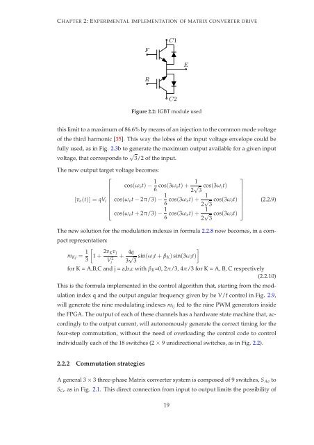
Figure 2.2: IGBT module used<br />
this limit to a maximum <strong>of</strong> 86.6% by means <strong>of</strong> an injection to the common mode voltage<br />
<strong>of</strong> the third harmonic [35]. This way the lobes <strong>of</strong> the input voltage envelope could be<br />
fully used, as in Fig. 2.3b to generate the maximum output available for a given input<br />
voltage, that corresponds to √ 3/2 <strong>of</strong> the input.<br />
The new output target voltage becomes:<br />
⎡<br />
⎢ cos(ωot)−<br />
⎢<br />
[vo(t)] = qVi<br />
⎢<br />
⎣<br />
1<br />
1<br />
cos(3ωot)+<br />
6 2 √ 3 cos(3ωit)<br />
cos(ωot− 2π/3)− 1<br />
1<br />
cos(3ωot)+<br />
6 2 √ 3 cos(3ωit)<br />
cos(ωot+ 2π/3)− 1<br />
1<br />
cos(3ωot)+<br />
6 2 √ 3 cos(3ωit)<br />
⎤<br />
⎥<br />
⎦<br />
(2.2.9)<br />
The new solution for the modulation indexes in formula 2.2.8 now becomes, in a com-<br />
pact representation:<br />
mKj = 1<br />
3<br />
<br />
1+ 2vKvj<br />
V2 +<br />
i<br />
4q<br />
3 √ 3 sin(ωit+ βK) sin(3ωit)<br />
for K = A,B,C and j = a,b,c with βK=0, 2π/3, 4π/3 for K = A, B, C respectively<br />
(2.2.10)<br />
This is the formula implemented in the control algorithm that, starting from the mod-<br />
ulation index q and the output angular frequency given by he V/f control in Fig. 2.9,<br />
will generate the nine modulating indexes mij fed to the nine PWM generators inside<br />
the FPGA. The output <strong>of</strong> each <strong>of</strong> these channels has a hardware state machine that, ac-<br />
cordingly to the output current, will autonomously generate the correct timing for the<br />
four-step commutation, without the need <strong>of</strong> overloading the control code to control<br />
individually each <strong>of</strong> the 18 switches (2×9unidirectional switches, as in Fig. 2.2).<br />
2.2.2 Commutation strategies<br />
A general 3×3 three-phase Matrix converter system is composed <strong>of</strong> 9 switches, SAa to<br />
SCc as in Fig. 2.1. This direct connection from input to output limits the possibility <strong>of</strong><br />
19


