TECHNICAL NOTES ON THE EEC-IV MCU - Auto diagnostics
TECHNICAL NOTES ON THE EEC-IV MCU - Auto diagnostics
TECHNICAL NOTES ON THE EEC-IV MCU - Auto diagnostics
You also want an ePaper? Increase the reach of your titles
YUMPU automatically turns print PDFs into web optimized ePapers that Google loves.
Eectch98-Part2.fm<br />
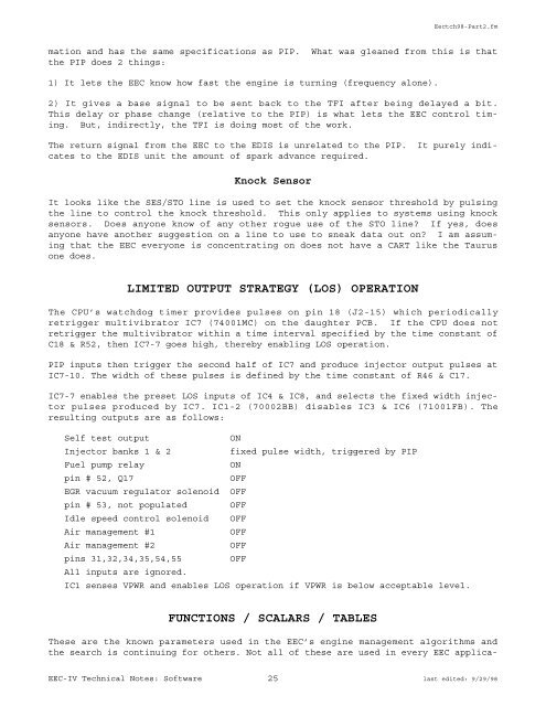
mation and has the same specifications as PIP. What was gleaned from this is that<br />
the PIP does 2 things:<br />
1) It lets the <strong>EEC</strong> know how fast the engine is turning (frequency alone).<br />
2) It gives a base signal to be sent back to the TFI after being delayed a bit.<br />
This delay or phase change (relative to the PIP) is what lets the <strong>EEC</strong> control timing.<br />
But, indirectly, the TFI is doing most of the work.<br />
The return signal from the <strong>EEC</strong> to the EDIS is unrelated to the PIP. It purely indicates<br />
to the EDIS unit the amount of spark advance required.<br />
Knock Sensor<br />
It looks like the SES/STO line is used to set the knock sensor threshold by pulsing<br />
the line to control the knock threshold. This only applies to systems using knock<br />
sensors. Does anyone know of any other rogue use of the STO line? If yes, does<br />
anyone have another suggestion on a line to use to sneak data out on? I am assuming<br />
that the <strong>EEC</strong> everyone is concentrating on does not have a CART like the Taurus<br />
one does.<br />
LIMITED OUTPUT STRATEGY (LOS) OPERATI<strong>ON</strong><br />
The CPU’s watchdog timer provides pulses on pin 18 (J2-15) which periodically<br />
retrigger multivibrator IC7 (74001MC) on the daughter PCB. If the CPU does not<br />
retrigger the multivibrator within a time interval specified by the time constant of<br />
C18 & R52, then IC7-7 goes high, thereby enabling LOS operation.<br />
PIP inputs then trigger the second half of IC7 and produce injector output pulses at<br />
IC7-10. The width of these pulses is defined by the time constant of R46 & C17.<br />
IC7-7 enables the preset LOS inputs of IC4 & IC8, and selects the fixed width injector<br />
pulses produced by IC7. IC1-2 (70002BB) disables IC3 & IC6 (71001FB). The<br />
resulting outputs are as follows:<br />
Self test output <strong>ON</strong><br />
Injector banks 1 & 2 fixed pulse width, triggered by PIP<br />
Fuel pump relay <strong>ON</strong><br />
pin # 52, Q17 OFF<br />
EGR vacuum regulator solenoid OFF<br />
pin # 53, not populated OFF<br />
Idle speed control solenoid OFF<br />
Air management #1 OFF<br />
Air management #2 OFF<br />
pins 31,32,34,35,54,55 OFF<br />
All inputs are ignored.<br />
IC1 senses VPWR and enables LOS operation if VPWR is below acceptable level.<br />
FUNCTI<strong>ON</strong>S / SCALARS / TABLES<br />
These are the known parameters used in the <strong>EEC</strong>’s engine management algorithms and<br />
the search is continuing for others. Not all of these are used in every <strong>EEC</strong> applica-<br />
<strong>EEC</strong>-<strong>IV</strong> Technical Notes: Software 25 last edited: 9/29/98


