TECHNICAL NOTES ON THE EEC-IV MCU - Auto diagnostics
TECHNICAL NOTES ON THE EEC-IV MCU - Auto diagnostics
TECHNICAL NOTES ON THE EEC-IV MCU - Auto diagnostics
You also want an ePaper? Increase the reach of your titles
YUMPU automatically turns print PDFs into web optimized ePapers that Google loves.
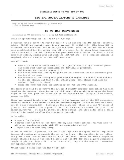
Technical Notes on The <strong>EEC</strong>-<strong>IV</strong> <strong>MCU</strong><br />
<strong>EEC</strong> EFI MODIFICATI<strong>ON</strong>S & UPGRADES<br />
Compiled by Tom Cloud <br />
(font is Courier New)<br />
SD TO MAF C<strong>ON</strong>VERSI<strong>ON</strong><br />
Information on MAF conversion sent to me by Bob Nell bnell@utk.edu<br />
(This is specifically for ’87-’88 SD 5.0 Mustangs.)<br />
Eectch98-Part5.fm<br />
I started with a stock ’88 Speed Density 5.0 LX and got the MAF sensor, bracket,<br />
tubing, <strong>EEC</strong>-<strong>IV</strong> and manual tranny from a wrecked ’91 LX MAF 5.0. (The Cobra MAF is<br />
different than the GT/LX MAF in that,in the Cobra, both the <strong>EEC</strong> and the MAF have<br />
been recalibrated for 24# rather than 19# injectors. So, if using Cobra components,<br />
use a Cobra <strong>EEC</strong>.) The MAF connector was purchased from a dealer for about $10 and<br />
came with solder, shrink wrap and splicing instructions. If a complete harness is<br />
required, there are companies that sell used ones.<br />
You will need:<br />
• Mass Air Flow meter calibrated for the injector size (using mismatched parts<br />
can cause part throttle detonation and drivability problems).<br />
• MAF bracket and mounting screws (3).<br />
• MAF 4-wire connector, wiring to go to the <strong>EEC</strong> connector and <strong>EEC</strong> connector pins<br />
for two of the wires.<br />
• MAF ductwork -- the tubing that goes from the engine to the MAF, from the MAF<br />
to the air cleaner and then to the intake scoop. Some clamps will also be<br />
needed to hold it in place.<br />
• Extra <strong>EEC</strong> connector pins for hooking up the VSS and FPM2 signals.<br />
The first step will be to remove the old speed density computer from behind the kick<br />
panel on the passenger side. Remove the kick panel, the retaining screw on the lower<br />
right of the ECM, push the wires out of the way and then, using a 10 mm wrench,<br />
remove the ECM.<br />
There are unused female pins (sockets) in the harness end of the <strong>EEC</strong> connector.<br />
Seven of these will be needed to add the necessary inputs (it can be done with four,<br />
but it’s not recommended). Looking at the connector, there is a red "H" piece of<br />
plastic that needs to be popped out of the connector to allow the pins to be<br />
inserted/removed. It can be pushed out from behind (the wire side) then a small<br />
pick will be needed to allow the pins to be removed.<br />
To be added:<br />
• 4 Inputs for the MAF.<br />
• 2 Inputs from the VSS (if you don’t already have cruise control, you will have to<br />
add a new speedometer cable with VSS and appropriate wiring).<br />
• 1 Input from the Fuel Pump Relay.<br />
If cruise control is present, run the 2 VSS inputs to the speed control amplifier<br />
instead of routing wires outside the car to the tranny. The amplifier is the yellowish<br />
plastic box located near the driver’s left foot. There are also a couple of<br />
pinout changes between the speed density and the MAF <strong>EEC</strong> that require swapping a<br />
couple of pin positions - if it’s as remembered, they are the TAB/TAD (thermactor<br />
air bypass/diverter) pins.<br />
Attach these 4 wires from the MAF to the <strong>EEC</strong><br />
<strong>EEC</strong>-<strong>IV</strong> Technical Notes: Modifications/Upgrades56 last edited: 9/29/98


