Vaporization of JP-8 Jet Fuel in a Simulated Aircraft Fuel Tank ...
Vaporization of JP-8 Jet Fuel in a Simulated Aircraft Fuel Tank ...
Vaporization of JP-8 Jet Fuel in a Simulated Aircraft Fuel Tank ...

You also want an ePaper? Increase the reach of your titles
YUMPU automatically turns print PDFs into web optimized ePapers that Google loves.
s<strong>in</strong>ce jet fuel is typically not flammable under 100°F [13]. On the ground, the top w<strong>in</strong>g<br />
surfaces can be heated by sunlight. However, this is generally not a critical condition<br />
because the liquid fuel is on the bottom fuel tank surface, and significant time is required<br />
to heat the liquid to create a flammable mixture. The extra fuel required for larger<br />
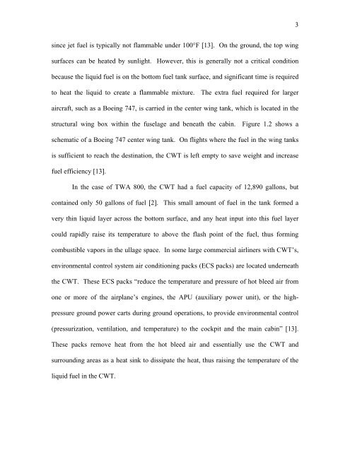
aircraft, such as a Boe<strong>in</strong>g 747, is carried <strong>in</strong> the center w<strong>in</strong>g tank, which is located <strong>in</strong> the<br />
structural w<strong>in</strong>g box with<strong>in</strong> the fuselage and beneath the cab<strong>in</strong>. Figure 1.2 shows a<br />
schematic <strong>of</strong> a Boe<strong>in</strong>g 747 center w<strong>in</strong>g tank. On flights where the fuel <strong>in</strong> the w<strong>in</strong>g tanks<br />
is sufficient to reach the dest<strong>in</strong>ation, the CWT is left empty to save weight and <strong>in</strong>crease<br />
fuel efficiency [13].<br />
In the case <strong>of</strong> TWA 800, the CWT had a fuel capacity <strong>of</strong> 12,890 gallons, but<br />
conta<strong>in</strong>ed only 50 gallons <strong>of</strong> fuel [2]. This small amount <strong>of</strong> fuel <strong>in</strong> the tank formed a<br />
very th<strong>in</strong> liquid layer across the bottom surface, and any heat <strong>in</strong>put <strong>in</strong>to this fuel layer<br />
could rapidly raise its temperature to above the flash po<strong>in</strong>t <strong>of</strong> the fuel, thus form<strong>in</strong>g<br />
combustible vapors <strong>in</strong> the ullage space. In some large commercial airl<strong>in</strong>ers with CWT’s,<br />
environmental control system air condition<strong>in</strong>g packs (ECS packs) are located underneath<br />
the CWT. These ECS packs “reduce the temperature and pressure <strong>of</strong> hot bleed air from<br />
one or more <strong>of</strong> the airplane’s eng<strong>in</strong>es, the APU (auxiliary power unit), or the high-<br />
pressure ground power carts dur<strong>in</strong>g ground operations, to provide environmental control<br />
(pressurization, ventilation, and temperature) to the cockpit and the ma<strong>in</strong> cab<strong>in</strong>” [13].<br />
These packs remove heat from the hot bleed air and essentially use the CWT and<br />
surround<strong>in</strong>g areas as a heat s<strong>in</strong>k to dissipate the heat, thus rais<strong>in</strong>g the temperature <strong>of</strong> the<br />
liquid fuel <strong>in</strong> the CWT.<br />
3