


You also want an ePaper? Increase the reach of your titles
YUMPU automatically turns print PDFs into web optimized ePapers that Google loves.
Field Testing and Instrumentation <strong>of</strong> <strong>Railway</strong> <strong>Vehicle</strong>s 433<br />
V<br />
Balancing<br />
Potentiometer<br />
is exercised, results from such set-ups may be used with areasonable degree <strong>of</strong> confidence. Where<br />
long cableruns are used, it is essential that the shunt resistanceisapplied across the gauge with the<br />
cable in place to ensure that the effects <strong>of</strong> cable resistance are accounted for in the calibration.<br />
Abridge may contain one, two, or four strain gauges in the arrangements showninFigure13.11,<br />
and these are knownasa 1<br />
1<br />
1<br />
4 -bridge, 2 -bridge and full bridge, respectively. A 4 -bridge will have the<br />
lowest sensitivity <strong>of</strong> these three arrangements. If no precautions are taken it may also produce errors<br />
if the gauges used are sensitive to thermal effects. In order to prevent this, one <strong>of</strong> the resistors<br />
adjacent to the active gauge may be replacedwith a“dummy” gauge. This will be an identical strain<br />
gauge to the active one that is subject to the same environmental conditions but is not subject<br />
to loading, achieved, for example, by mounting it on an unstressed part <strong>of</strong> the test component.<br />
Both gauges will be exposedtoany temperature changes and the effect is to cancelout any resulting<br />
unbalance on the bridge due to thermal effects. A 1<br />
2 -bridge will have ahigher sensitivity than a<br />
1<br />
4 -bridge as the additional strain gauge will produce alarger unbalanced voltage across the<br />
Wheatstone bridge. The presence <strong>of</strong> two active gauges will also cancel out any thermal effects as<br />
described above. Afull bridge will have the greatest sensitivity <strong>of</strong> the three arrangements and will<br />
similarly be self-compensating for temperature changes (Figure 13.11).<br />
Strain gauges are available that are self-compensating for temperature changesand the need for<br />
dummy gauges is therefore eliminated. However, changes intemperature can also affect the<br />
resistance <strong>of</strong>the lead wires and connectors and, if no dummy is present, such changes may<br />
unbalance the bridge resulting in errors in the strain measurement. Such errors can be minimised by<br />
the use <strong>of</strong> a“three-wire” arrangement such as that described in. 6<br />
It should be noted that the outputvoltage changesfrom strain bridges are usually very small and<br />
therefore shouldbeamplified as close to the bridge as possible. Onceagain, cabling shouldbefully<br />
screened and carefully installedtoprevent unwanted noisefrom interfering with the testdata.Itmay<br />
be advisable toinclude dummy gauges in the system that are subject to the same environmental<br />
conditions, wiring and connection arrangements as the active gauges but are not subjected to strain.<br />
These can be used to assist in determining the level <strong>of</strong>noise present.<br />
D. F ORCE-M EASURING W HEELSETS<br />
R 3<br />
R 1<br />
Recently proposed European standards 1,2 call for the assessment <strong>of</strong> wheel–rail forces —track<br />
forces —innewly developed or essentially modified main line rail vehicles, particularly for those<br />
operating athigher speeds. National standards and practices <strong>of</strong>ten call for track force assessment<br />
I 1 I 2<br />
Voltmeter<br />
I 3 I 4<br />
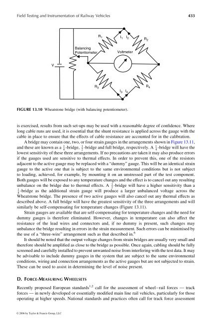
FIGURE 13.10 Wheatstone bridge (with balancing potentiometer).<br />
© 2006 by Taylor & Francis Group, LLC<br />
R 2<br />
R 4


