


Create successful ePaper yourself
Turn your PDF publications into a flip-book with our unique Google optimized e-Paper software.
Field Testing and Instrumentation <strong>of</strong> <strong>Railway</strong> <strong>Vehicle</strong>s 431<br />
The change in resistance <strong>of</strong>the gauge is related to the strain (i.e., the change in length <strong>of</strong> the<br />
gauge) by aconstant known asthe gauge factor.<br />
since strain is defined as 1 ¼ D L = L<br />
k ¼<br />
k ¼<br />
Gauge Length &<br />
Sensing Direction<br />
FIGURE 13.8 Foil strain gauge (courtesy <strong>of</strong> Micro Measurements Inc.). Source: From Micro Measurements<br />
Catalogue. With permission.<br />
D R = R<br />
D L = L<br />
D R = R<br />
1<br />
where k ¼ gauge factor; D R ¼ change <strong>of</strong> resistance; R ¼ unstrained resistance; D L ¼ change<br />
in gauge length; L ¼ unstrained gauge length; and 1 ¼ strain (normally quoted in terms <strong>of</strong><br />
micro-strain).<br />
The higherthe gauge factor,the higherthe sensitivity <strong>of</strong> the gauge. Good linearity is alsoakey<br />
requirement for accuratemeasurement; foilstraingauges typically have gauge factorsaround k ¼ 2<br />
and linearity varying from ^ 0.1% at 4000 m 1 to ^ 1% at 10,000 m 1 .Many configurations <strong>of</strong> foil<br />
strain gauges are available for avariety <strong>of</strong> strain measuring applications, aselection <strong>of</strong> which are<br />
shown in Figure13.9.Less commonly used are thick-film and semi-conductor strain gauges.These<br />
have considerably higher sensitivity than foil gauges with k ¼ 10 to 20 and k < 50, respectively.<br />
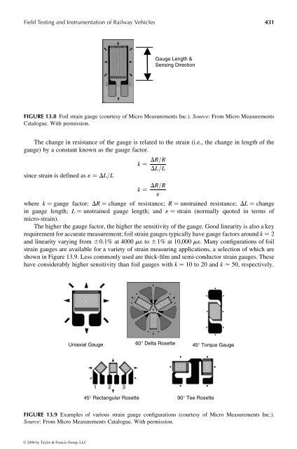
Uniaxial Gauge 60° Delta Rosette 45° Torque Gauge<br />
45° Rectangular Rosette 90° Tee Rosette<br />
FIGURE 13.9 Examples <strong>of</strong> various strain gauge configurations (courtesy <strong>of</strong> Micro Measurements Inc.).<br />
Source: From Micro Measurements Catalogue. With permission.<br />
© 2006 by Taylor & Francis Group, LLC


