


Create successful ePaper yourself
Turn your PDF publications into a flip-book with our unique Google optimized e-Paper software.
Field Testing and Instrumentation <strong>of</strong> <strong>Railway</strong> <strong>Vehicle</strong>s 451<br />
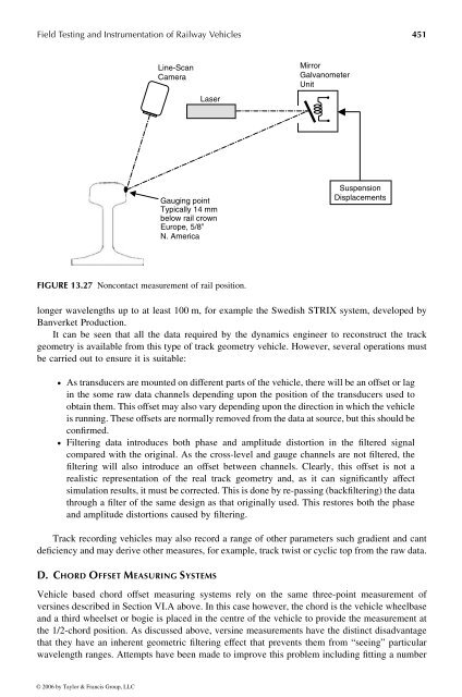
Line-Scan<br />
Camera<br />
Laser<br />
Gauging point<br />
Typically 14 mm<br />
below rail crown<br />
Europe, 5/8”<br />
N. America<br />
FIGURE 13.27 Noncontact measurement <strong>of</strong> rail position.<br />
longer wavelengths up to at least 100 m, for example the Swedish STRIX system, developed by<br />
Banverket Production.<br />
It can be seen that all the data required bythe dynamics engineer to reconstruct the track<br />
geometry is available from this type <strong>of</strong> track geometry vehicle. However, several operations must<br />
be carried out to ensure itissuitable:<br />
† As transducers are mounted on different parts <strong>of</strong> the vehicle, there will be an <strong>of</strong>fset or lag<br />
in the some raw data channels depending upon the position <strong>of</strong> the transducers used to<br />
obtain them. This <strong>of</strong>fset may also vary depending upon the direction in which the vehicle<br />
is running. These <strong>of</strong>fsets are normally removed from the data at source, but this should be<br />
confirmed.<br />
† Filtering data introduces both phase and amplitude distortion in the filtered signal<br />
compared with the original. As the cross-level and gauge channels are not filtered, the<br />
filtering will also introduce an <strong>of</strong>fset between channels. Clearly, this <strong>of</strong>fset is not a<br />
realistic representation <strong>of</strong> the real track geometry and, as it can significantly affect<br />
simulation results, it must be corrected. This is done by re-passing (backfiltering) the data<br />
through afilter <strong>of</strong> the same design as that originally used. This restores both the phase<br />
and amplitude distortions caused byfiltering.<br />
Track recording vehicles may also record arange <strong>of</strong> other parameters such gradient and cant<br />
deficiency and may derive othermeasures, for example, track twistorcyclic top from the raw data.<br />
D. C HORD O FFSET M EASURING S YSTEMS<br />
Mirror<br />
Galvanometer<br />
Unit<br />
Suspension<br />
Displacements<br />
<strong>Vehicle</strong> based chord <strong>of</strong>fset measuring systems rely on the same three-point measurement <strong>of</strong><br />
versines described in Section VI.A above. In this case however, the chord is the vehicle wheelbase<br />
and athird wheelset or bogie is placed in the centre <strong>of</strong> the vehicle to provide the measurement at<br />
the 1/2-chord position. As discussed above, versine measurements have the distinct disadvantage<br />
that they have an inherent geometric filtering effect that prevents them from “seeing” particular<br />
wavelength ranges. Attempts have been made toimprove this problem including fitting anumber<br />
© 2006 by Taylor & Francis Group, LLC


