


You also want an ePaper? Increase the reach of your titles
YUMPU automatically turns print PDFs into web optimized ePapers that Google loves.
428<br />
Relative Sensitivity<br />
30<br />
dB<br />
20<br />
10<br />
0<br />
− 10<br />
− 20<br />
− 30<br />
Useful Frequency Range<br />
10% limit 0.3 f m<br />
3dBlimit 0.5 f m<br />
Main Axis Sensitivity<br />
Transverse Sensitivity<br />
− 40<br />
0.0001 0.001 0.01<br />
<strong>Handbook</strong> <strong>of</strong> <strong>Railway</strong> <strong>Vehicle</strong> <strong>Dynamics</strong><br />
Transverse<br />
Resonance<br />
Frequency<br />
Proportion <strong>of</strong> Mounted Resonance Frequency<br />
Mounted<br />
Resonance<br />
Frequency<br />
f m<br />
0.1 1 10<br />
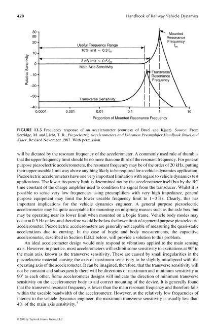
FIGURE 13.5 Frequency response <strong>of</strong> an accelerometer (courtesy <strong>of</strong> Bruel and Kjaer). Source: From<br />
Serridge, M. and Licht, T. R., Piezoelectric Accelerometers and Vibration Preamplifier <strong>Handbook</strong> Bruel and<br />
Kjaer, Revised November 1987. With permission.<br />
will be dictated by the resonant frequency<strong>of</strong>the accelerometer. Acommonly used rule<strong>of</strong>thumb is<br />
that the upper frequency limit shouldbenomore than one third <strong>of</strong> the resonant frequency. Forgeneral<br />
purposepiezoelectric accelerometers, the resonant frequencymay be <strong>of</strong> the order <strong>of</strong> 20 kHz, putting<br />
their upper useable limit way above anything likely to be requiredfor avehicle dynamics application.<br />
Piezoelectric accelerometers have one very important limitation with regard to vehicle dynamics test<br />
applications. Thelower frequency limit is determined not by the accelerometer itself but by the RC<br />
time constant <strong>of</strong> the charge amplifier used to condition the signal from the transducer. Whilst it is<br />
possible tosense very low frequencies using preamplifiers with very high impedance, general<br />
purpose equipment may limit the lower useable frequency limit to 1–3Hz. Clearly, this has<br />
important implications for the vehicle dynamics engineer. A general purpose piezoelectric<br />
accelerometer may be quite acceptable for mounting on unsprung masses such as the axle box, but<br />
may be operating near its lower limit when mounted on abogie frame. <strong>Vehicle</strong> body modes may<br />
occur at 0.5 Hz or less and therefore would be below the lower limit <strong>of</strong> ageneral purposepiezoelectric<br />
accelerometer. Piezoelectric accelerometers are generally not capable <strong>of</strong> measuring the quasi-static<br />
accelerations due to curving. In the case <strong>of</strong> bogie and body measurements, the capacitive<br />
accelerometer, described in Section II.B.2 below, will provide asolution to this problem.<br />
An ideal accelerometer design would only respond to vibrations applied to the main sensing<br />
axis. However, in practice, mostaccelerometers will exhibit somesensitivity to excitations at 908 to<br />
the main axis, known asthe transverse sensitivity. These are caused bysmall irregularities in the<br />
piezoelectric material causing the axis <strong>of</strong> maximum sensitivity to be slightly misaligned with the<br />
operating axis <strong>of</strong> the accelerometer. It can be imagined, therefore, that the transverse sensitivity will<br />
not be constant and subsequently there will be directions <strong>of</strong> maximum and minimum sensitivity at<br />
908 to each other. Some accelerometer designs will indicate the direction <strong>of</strong> minimum transverse<br />
sensitivity on the accelerometer body to aid correct mounting <strong>of</strong> the device. It is generally found<br />
that the transverse resonant frequencyislower than the main resonant frequencyand therefore falls<br />
within the useable bandwidth <strong>of</strong> the accelerometer. However, at the relatively low frequencies <strong>of</strong><br />
interest to the vehicle dynamics engineer, the maximum transverse sensitivity is usually less than<br />
4% <strong>of</strong> the main axis sensitivity. 4<br />
© 2006 by Taylor & Francis Group, LLC


