


You also want an ePaper? Increase the reach of your titles
YUMPU automatically turns print PDFs into web optimized ePapers that Google loves.
Field Testing and Instrumentation <strong>of</strong> <strong>Railway</strong> <strong>Vehicle</strong>s 447<br />
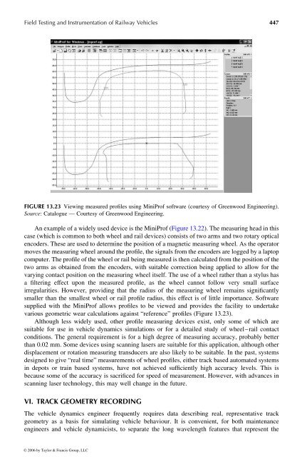
FIGURE 13.23 Viewing measured pr<strong>of</strong>iles using MiniPr<strong>of</strong> s<strong>of</strong>tware (courtesy <strong>of</strong> Greenwood Engineering).<br />
Source: Catalogue —Courtesy <strong>of</strong> Greenwood Engineering.<br />
An example <strong>of</strong> awidely used device is the MiniPr<strong>of</strong> (Figure13.22). Themeasuring head in this<br />
case (whichiscommon to both wheel and rail devices) consists<strong>of</strong>two arms and two rotary optical<br />
encoders. These are used to determinethe position <strong>of</strong> amagnetic measuring wheel. As the operator<br />
moves the measuring wheel aroundthe pr<strong>of</strong>ile, the signals from the encoders are logged by alaptop<br />
computer. Thepr<strong>of</strong>ile<strong>of</strong>the wheel or rail being measured is then calculated from the position <strong>of</strong> the<br />
two arms as obtained from the encoders, with suitable correction being applied to allow for the<br />
varying contact position on the measuring wheel itself. The use <strong>of</strong> awheel rather than astylus has<br />
a filtering effect upon the measured pr<strong>of</strong>ile, as the wheel cannot follow very small surface<br />
irregularities. However, providing that the radius <strong>of</strong> the measuring wheel remains significantly<br />
smaller than the smallest wheel or rail pr<strong>of</strong>ile radius, this effect is <strong>of</strong> little importance. S<strong>of</strong>tware<br />
supplied with the MiniPr<strong>of</strong> allows pr<strong>of</strong>iles to be viewed and provides the facility to undertake<br />
various geometric wear calculations against “reference” pr<strong>of</strong>iles (Figure 13.23).<br />
Although less widely used, other pr<strong>of</strong>ile measuring devices exist, only some <strong>of</strong>which are<br />
suitable for use invehicle dynamics simulations or for adetailed study <strong>of</strong> wheel–rail contact<br />
conditions. The general requirement is for ahigh degree <strong>of</strong> measuring accuracy, probably better<br />
than 0.02 mm. Some devices using scanning lasers are suitable for this application, although other<br />
displacement or rotation measuring transducers are also likely to be suitable. In the past, systems<br />
designed to give “real time” measurements <strong>of</strong> wheel pr<strong>of</strong>iles, either track based automated systems<br />
in depots or train based systems, have not achieved sufficiently high accuracy levels. This is<br />
because some <strong>of</strong>the accuracy is sacrificed for speed <strong>of</strong> measurement. However, with advances in<br />
scanning laser technology, this may well change in the future.<br />
VI. TRACK GEOMETRY RECORDING<br />
The vehicle dynamics engineer frequently requires data describing real, representative track<br />
geometry as abasis for simulating vehicle behaviour. Itisconvenient, for both maintenance<br />
engineers and vehicle dynamicists, to separate the long wavelength features that represent the<br />
© 2006 by Taylor & Francis Group, LLC


