


Create successful ePaper yourself
Turn your PDF publications into a flip-book with our unique Google optimized e-Paper software.
438<br />
The overall goal is to achieve output signals proportional to the applied loads with aminimum<br />
<strong>of</strong> cross talk and parasitic effects. Several techniques are used for this purpose, for example, in<br />
France, Germany, Sweden, U.S.A., and China. The selection <strong>of</strong> locations for the strain gauges,their<br />
connection in bridges and the additional data processing, may vary considerably from one<br />
laboratory to another. The design, calibration, and operation <strong>of</strong> this type <strong>of</strong> equipment is ahighly<br />
specialised subject and adetailed description is beyond the scope <strong>of</strong> this chapter.<br />
Theprinciple advantage <strong>of</strong> the “wheel web method” is that it is possible to measure the Y and Q<br />
forces continuously quite close to the wheel–rail interface and hence most <strong>of</strong> the dynamic effect<br />
from the unsprung mass isincluded inthe measured data. It is possible to measure quite highfrequencyforces<br />
(up to at least 100 Hz). The measuring accuracy may be good or at least acceptable<br />
(within 5–10% under normal conditions) if wheels and the whole system are properly designed and<br />
calibrated. The major drawback isthe volume <strong>of</strong> work required for system design and calibration,<br />
requiring specialised knowledge which generally makes the technique very expensive. Afurther<br />
drawback isthat the instrumented wheelsets must very <strong>of</strong>ten be specifically designed for the type<br />
<strong>of</strong> vehicle to be tested.<br />
E. V EHICLE S PEED AND P OSITION M EASUREMENT<br />
Aprerequisite <strong>of</strong> almost all on-track testing applications will be the ability to determine vehicle<br />
speed and position. This section discusses the most commonly used approaches to this problem.<br />
1. The ACTachogenerator<br />
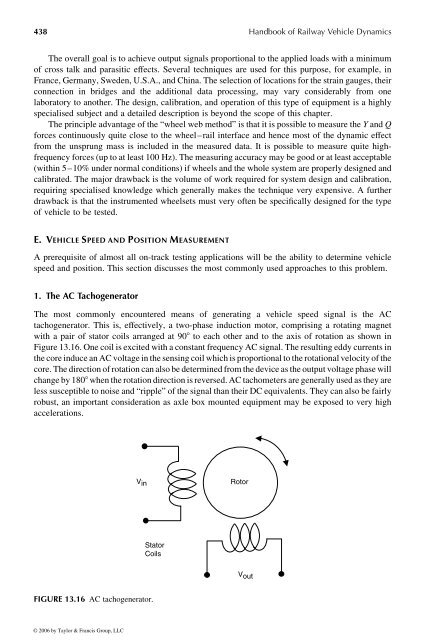
The most commonly encountered means <strong>of</strong> generating a vehicle speed signal is the AC<br />
tachogenerator. This is, effectively, atwo-phase induction motor, comprising arotating magnet<br />
with apair <strong>of</strong> stator coils arranged at 908 to each other and to the axis <strong>of</strong> rotation as shown in<br />
Figure13.16.One coil is excitedwith aconstant frequencyACsignal. The resulting eddy currents in<br />
the core induceanACvoltage in the sensing coil which is proportional to the rotationalvelocity <strong>of</strong> the<br />
core.The direction <strong>of</strong> rotation can also be determined from the device as the outputvoltage phase will<br />
change by 1808 when the rotation direction is reversed. AC tachometers are generally used as they are<br />
less susceptibletonoise and “ripple” <strong>of</strong> the signal than their DC equivalents. They can also be fairly<br />
robust, an important consideration as axle box mounted equipment may be exposed to very high<br />
accelerations.<br />
V in<br />
FIGURE 13.16 AC tachogenerator.<br />
© 2006 by Taylor & Francis Group, LLC<br />
Stator<br />
Coils<br />
Rotor<br />
V out<br />
<strong>Handbook</strong> <strong>of</strong> <strong>Railway</strong> <strong>Vehicle</strong> <strong>Dynamics</strong>


