


Create successful ePaper yourself
Turn your PDF publications into a flip-book with our unique Google optimized e-Paper software.
450<br />
remove the long wavelength design information, effectively creating amoving average datum<br />
for the measurement <strong>of</strong> the shorter wavelength features.<br />
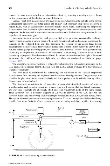
Vertical (track top) measurements are made using one wheelset on the vehicle as the sensor.<br />
Displacement transducers are fitted across the primary and secondary suspension as shown in<br />
Figure 13.26, with an accelerometer mounted directly above them. Subtracting the suspension<br />
displacementsfrom the body displacement (doubleintegratedfrom the acceleration) gives the track<br />
top pr<strong>of</strong>ile. As the suspension movements are removed from the final answer,the system is effective<br />
regardless <strong>of</strong> suspension type.<br />
Noncontact measurement <strong>of</strong> the track gauge at high speed presents aconsiderable challenge.<br />
Early systems projected anarrow beam <strong>of</strong> light onto the railhead and used cameras to measure the<br />
intensity <strong>of</strong> the reflected light and thus determine the location <strong>of</strong> the gauge face. Recent<br />
developments include using alaser beam is guided onto apoint 14 mm below the crown <strong>of</strong> the<br />
rail, the normal gauge measuring point, by amirror. This mirror is “steered” by agalvanometer,<br />
responding to suspension displacement measurements. Alternatively, a fanned array <strong>of</strong> laser<br />
beams may be projected directly onto the railhead. In either case the reflectedlaser light is then used<br />
to measure the position <strong>of</strong> left and right rails, and these are combined toobtain the gauge<br />
(Figure 13.27).<br />
Thelateral irregularity <strong>of</strong> the track is obtainedbysubtracting the rail position, measured by the<br />
laser displacement sensors described above from the inertial datum produced by abody mounted<br />
lateral accelerometer.<br />
The cross-level is determined by subtracting the difference in the vertical suspension<br />
displacements from the body roll angle obtained from an on-board gyroscope. The gyroscope also<br />
provides the plan view rate <strong>of</strong> turn <strong>of</strong> the body and this, together with the vehicle velocity, allows<br />
the curvature to be calculated.<br />
The foregoing description is, <strong>of</strong> necessity, a somewhat simplified version <strong>of</strong> what is<br />
asophisticated and complex measuring system. Itisworth noting that the lateral irregularity<br />
and curvature channels are effectively short and long wavelength parts <strong>of</strong> the same signal.<br />
Track geometry data is normally supplied at0.2–0.25 mintervals in the U.K. and will not<br />
therefore adequately capture very short wavelength features, less than 1.5 m, such as dipped joints.<br />
The system alsodoes not capture wavelength greater than 70 m, and beinginertially based will only<br />
provide data above 30 km/h. Other systems are now becoming available, capable <strong>of</strong> measuring<br />
z+ u<br />
u<br />
z<br />
<strong>Vehicle</strong> Floor<br />
Bogie Frame<br />
Accelerometer<br />
Displacement<br />
Transducers<br />
FIGURE 13.26 Vertical measuring system schematic.<br />
© 2006 by Taylor & Francis Group, LLC<br />
d 2<br />
dt2 (z+u)<br />
<strong>Handbook</strong> <strong>of</strong> <strong>Railway</strong> <strong>Vehicle</strong> <strong>Dynamics</strong><br />
+<br />
u<br />
Double<br />
Integrator<br />
(z+u)<br />
Adder<br />
z r<br />
From left side z L<br />
Difference


