


Create successful ePaper yourself
Turn your PDF publications into a flip-book with our unique Google optimized e-Paper software.
Field Testing and Instrumentation <strong>of</strong> <strong>Railway</strong> <strong>Vehicle</strong>s 427<br />
arrangement, the amplitude <strong>of</strong>displacement <strong>of</strong> the seismic mass will be directly proportional<br />
acceleration exciting the transducer. It follows, therefore, that accelerometers work by sensing the<br />
relative displacement <strong>of</strong> the seismic mass with respect to the transducer casing. It can be shown,<br />
mathematically, 3 that the maximum useful frequency range <strong>of</strong> an accelerometer, around 20–30%<br />
<strong>of</strong> the transducers natural frequency, is achieved with adamping ratio <strong>of</strong> 0.7. This damping ratio<br />
also provides almost zero phase distortion.<br />
1. Piezoelectric Accelerometers<br />
The most commonly used type <strong>of</strong> accelerometer is the piezoelectric accelerometer. The sensing<br />
element in such devices is aslice or disc <strong>of</strong> piezoelectric material. Such materials develop an<br />
electrical charge when they are subjected to mechanical stress. Anumber <strong>of</strong> naturally occurring<br />
materials exhibit this effect (e.g., quartz), but transducers typically employed man-made materials<br />
<strong>of</strong> afamily known as“ferroelectric ceramics.” 4<br />
Practical accelerometer designs typically employ aseismic mass resting upon, or suspended<br />
from, anumber <strong>of</strong> slices <strong>of</strong> the piezoelectric material. The vibration <strong>of</strong> the seismic mass within<br />
the accelerometer exerts aforce onthe piezoelectric material and acharge is developed that is<br />
proportional to the force exerted. Three common designs <strong>of</strong> accelerometer are illustrated in<br />
Figure 13.4 below.<br />
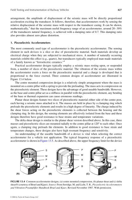
The centre mounted compression design isarelatively simple arrangement where the mass is<br />
mounted on acentre pillar with aspring to provide the preloading. The mass acts in compressionon<br />
the piezoelectric element. These designs have the advantage <strong>of</strong> good useable bandwidth. However,<br />
as the base and centre pillaract as astiffnessinparallel with the piezoelectric element, any bending<br />
<strong>of</strong> the base or thermal expansion can cause erroneous readings.<br />
Planar shear designs feature two slices <strong>of</strong> piezoelectric material either side <strong>of</strong> the centre post,<br />
each having aseismic mass attached to it. The masses are held in place by aclamping ring which<br />
preloads the piezoelectric elements and results in ahigh degree<strong>of</strong>linearity. The charge induced by<br />
the shear forces acting on the piezoelectric elements is collected between the housing and the<br />
clamping ring. In this design, the sensing elements are effectively isolated from the base and these<br />
designs therefore have good resistance to base strains and temperature variations.<br />
The delta shear design is similar to the planar shear version described above. In this case, three<br />
masses and piezoelectricslices are mounted radially to the centre pillar at 1208 to each other. Once<br />
again, aclamping ring preloads the elements. Inaddition to good resistance tobase strain and<br />
temperature changes, these designs also have high resonant frequency and sensitivity.<br />
An understanding <strong>of</strong>the useable bandwidth <strong>of</strong> adevice is vital when selecting the correct<br />
accelerometer for avehicle test application. The typical frequency response <strong>of</strong> apiezoelectric<br />
accelerometer is shown in Figure13.5.Asdescribed above, the upper frequency limit for the device<br />
FIGURE 13.4 Common accelerometer designs, (a) centre mounted compression, (b) planar shear and (c) delta<br />
shearw (courtesy <strong>of</strong> Bruel and Kjaer). Source:From Serridge, M. and Licht, T. R., Piezoelectric Accelerometers<br />
and Vibration Preamplifier <strong>Handbook</strong> Bruel and Kjaer,Revised November 1987. With permission.<br />
© 2006 by Taylor & Francis Group, LLC


