


Create successful ePaper yourself
Turn your PDF publications into a flip-book with our unique Google optimized e-Paper software.
Field Testing and Instrumentation <strong>of</strong> <strong>Railway</strong> <strong>Vehicle</strong>s 429<br />
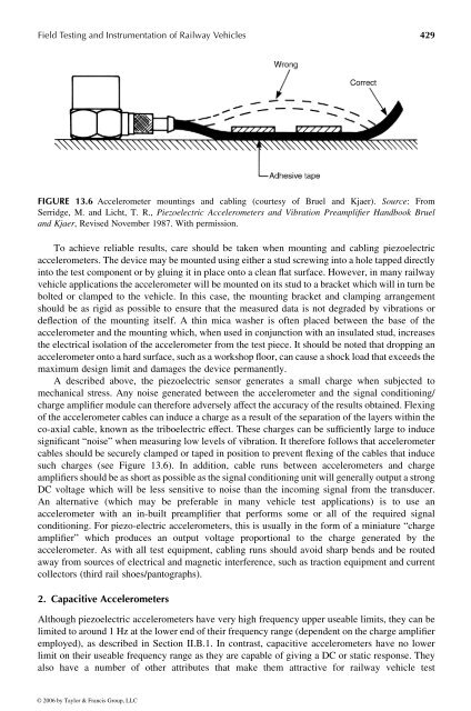
FIGURE 13.6 Accelerometer mountings and cabling (courtesy <strong>of</strong> Bruel and Kjaer). Source: From<br />
Serridge, M. and Licht, T. R., Piezoelectric Accelerometers and Vibration Preamplifier <strong>Handbook</strong> Bruel<br />
and Kjaer, Revised November 1987. With permission.<br />
To achieve reliable results, care should be taken when mounting and cabling piezoelectric<br />
accelerometers.The device may be mounted usingeither astud screwing into ahole tapped directly<br />
into the testcomponent or by gluing it in place onto aclean flat surface. However, in manyrailway<br />
vehicle applications the accelerometer will be mounted on its stud to abracket which will in turn be<br />
bolted or clamped tothe vehicle. In this case, the mounting bracket and clamping arrangement<br />
should be as rigid as possible to ensure that the measured data is not degraded by vibrations or<br />
deflection <strong>of</strong> the mounting itself. Athin mica washer is <strong>of</strong>ten placed between the base <strong>of</strong> the<br />
accelerometer and the mounting which, whenused in conjunction with an insulated stud, increases<br />
the electrical isolation <strong>of</strong> the accelerometer from the test piece. It shouldbenoted that dropping an<br />
accelerometer onto ahard surface, such as aworkshop floor, can cause ashock load that exceeds the<br />
maximum design limit and damages the device permanently.<br />
Adescribed above, the piezoelectric sensor generates asmall charge when subjected to<br />
mechanical stress. Any noise generated between the accelerometer and the signal conditioning/<br />
charge amplifier module can therefore adversely affect the accuracy <strong>of</strong> the results obtained. Flexing<br />
<strong>of</strong> the accelerometer cables can induceacharge as aresult <strong>of</strong> the separation <strong>of</strong> the layers within the<br />
co-axial cable, known asthe triboelectric effect. These charges can be sufficiently large to induce<br />
significant “noise” when measuring low levels <strong>of</strong> vibration. It therefore follows that accelerometer<br />
cables should besecurely clamped ortaped in position to prevent flexing <strong>of</strong> the cables that induce<br />
such charges (see Figure 13.6). In addition, cable runs between accelerometers and charge<br />
amplifiers should be as short as possible as the signal conditioning unit will generally outputastrong<br />
DC voltage which will be less sensitive to noise than the incoming signal from the transducer.<br />
An alternative (which may be preferable in many vehicle test applications) is to use an<br />
accelerometer with an in-built preamplifier that performs some orall <strong>of</strong> the required signal<br />
conditioning. For piezo-electric accelerometers, this is usually in the form <strong>of</strong> aminiature “charge<br />
amplifier” which produces an output voltage proportional to the charge generated by the<br />
accelerometer. As with all test equipment, cabling runs should avoid sharp bends and be routed<br />
away from sources <strong>of</strong> electrical and magnetic interference, such as traction equipment and current<br />
collectors (third rail shoes/pantographs).<br />
2. Capacitive Accelerometers<br />
Although piezoelectric accelerometers have very high frequency upper useable limits, they can be<br />
limited to around1Hz at the lower end <strong>of</strong> their frequencyrange (dependent on the charge amplifier<br />
employed), as described in Section II.B.1. In contrast, capacitive accelerometers have no lower<br />
limit on their useable frequency range as they are capable <strong>of</strong> giving aDCorstatic response. They<br />
also have a number <strong>of</strong> other attributes that make them attractive for railway vehicle test<br />
© 2006 by Taylor & Francis Group, LLC


