


Create successful ePaper yourself
Turn your PDF publications into a flip-book with our unique Google optimized e-Paper software.
448<br />
design layout <strong>of</strong> the track from the short wavelength features that form the variation from the design<br />
(i.e., the track irregularities). This usually results in adescription based on the following five<br />
geometrical terms:<br />
Curvature —the lateral design layout <strong>of</strong> the track radii (long wavelength). Curvature is defined<br />
as the inverse <strong>of</strong> the curve radius in units <strong>of</strong>rad/km. However curvature may also be quoted as<br />
a“versine” measurement in mm, this being the distance from the centre <strong>of</strong> achord <strong>of</strong> known<br />
length to the rail.<br />
Cant —the vertical difference in height <strong>of</strong> the left and right rails, (long wavelength).<br />
Lateral alignment —the short wavelength lateral track irregularities.<br />
Vertical alignment —the short wavelength vertical track irregularities.<br />
Gauge —the distancebetweenthe rails measured at aspecified distancebelowthe crown <strong>of</strong> the<br />
rail. This is typically 14mminthe U.K. and Europe and 5/8 in. in North America. Gauge may<br />
be given as an absolute value oravariation from anominal gauge (e.g., 1435mmEuropean<br />
standard gauge).<br />
The geometry <strong>of</strong> railway track may be recorded using one <strong>of</strong> several techniques.<br />
A. M ANUAL S URVEY<br />
The surveyor establishes adatum (or several datums)position on the site to be surveyed, usually by<br />
placing amarker in the ground.Atheodolite is then used to record the position <strong>of</strong> the left and right<br />
rail with reference to the datum position. Considerable care is required toproduce accurate results<br />
from these techniques. Good results have been achieved by using ahigh accuracy “autotracking”<br />
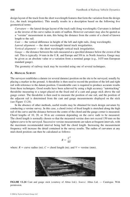
theodolite measuring to atarget placed on the fixed end <strong>of</strong> acant and gauge stick above the rail<br />
gauge corner. The theodolite is then used to measure the position <strong>of</strong> one rail, and the position <strong>of</strong><br />
the adjacent rail is determined from the cant and gauge measurements displayed on the stick<br />
(see Figure 13.24).<br />
In the absence <strong>of</strong> other methods, useful results may be obtained for track design curvature by<br />
conducting aversine survey. Inthis case, achord (wire) <strong>of</strong> fixed length is stretched along the high<br />
rail <strong>of</strong> the curve and the distancebetweenthe centre <strong>of</strong> the chord and the gauge corner is measured.<br />
Chord lengths <strong>of</strong> 10, 20, or 30 mare common depending on the curve radii to be measured.<br />
The chord length is normally chosen sothat the measured versine does not exceed 150 mm on the<br />
tightest curve to be surveyed. Successive versine measurements are takenatfrequent intervals, with<br />
the maximum recommended interval being half the chord length. Increasing the measurement<br />
frequency will increase the detail contained in the survey results. The radius <strong>of</strong> curvature at any<br />
mid-chord position can then be calculated as follows:<br />
R ¼<br />
where: R ¼ curve radius (m); C ¼ chord length (m); and V ¼ versine (mm).<br />
FIGURE 13.24 Cant and gauge stick (courtesy <strong>of</strong> Abtus Ltd.). Source: Abtus Ltd. —Catalogue. With<br />
permission.<br />
© 2006 by Taylor & Francis Group, LLC<br />
C 2<br />
8 V<br />
<strong>Handbook</strong> <strong>of</strong> <strong>Railway</strong> <strong>Vehicle</strong> <strong>Dynamics</strong>


