


Create successful ePaper yourself
Turn your PDF publications into a flip-book with our unique Google optimized e-Paper software.
Field Testing and Instrumentation <strong>of</strong> <strong>Railway</strong> <strong>Vehicle</strong>s 441<br />
known asDifferential GPS (DGPS) uses Earth based “reference stations” at known locations to<br />
determine corrections to the satellites transmitted positions. Using DGPS, accuracies <strong>of</strong> 1–5mor<br />
better may be achieved.<br />
For railway test applications, the GPS antenna is mounted on the ro<strong>of</strong> <strong>of</strong> the vehicle to ensure<br />
that the maximum number <strong>of</strong> satellites isvisible. However, since GPS is a“line-<strong>of</strong>-sight” system,<br />
deep cuttings, tunnels, high buildings, and other obstructions will prevent the system from working.<br />
In addition, it may be considered advisable to confirm the loggedlocation by “marking” the logged<br />
data, either by a manually activated signal against known locations (mileposts, etc.) or<br />
automatically by recording signals from trackside balises or signalling devices (e.g., AWS/TPWS<br />
loops in the U.K.).<br />
III. TEST EQUIPMENT CONFIGURATION AND ENVIRONMENT<br />
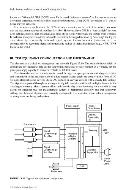
The elements <strong>of</strong> atypical test arrangement are shown in Figure 13.19.The example shown mightbe<br />
appropriate for gathering data on the suspension behaviour or ride comfort <strong>of</strong>avehicle, but the<br />
principles apply equally to many on-vehicle or lab test tasks.<br />
Data from the selected transducers is passed through the appropriate conditioning electronics<br />
and transmitted to the analogue side <strong>of</strong> adata logger. Such signals are usually in the form <strong>of</strong> DC<br />
voltages although some devices utilise AC voltage or varying current with asteady DC voltage.<br />
The signals are passed through an analogue to digital converter and stored in digital format in the<br />
data logger memory. Many systems allow real-time display <strong>of</strong> the incoming data and this is very<br />
useful for checking that the measurement system is performing correctly and that sensitivity<br />
settings for different channels are correctly configured. It is essential when vehicle acceptance<br />
or safety tests are being undertaken.<br />
Transducers<br />
Signal<br />
Conditioning /<br />
Amplifier<br />
Signal<br />
Conditioning /<br />
Amplifier<br />
Tachometer<br />
FIGURE 13.19 Typical test equipment configuration.<br />
© 2006 by Taylor & Francis Group, LLC<br />
Power Supply Printer /<br />
Chart Plotter<br />
Analogue<br />
to Digital<br />
Converter<br />
B<br />
u<br />
f<br />
f<br />
e<br />
r<br />
GPS<br />
Display /<br />
Supervising<br />
PC<br />
Memory<br />
Controller /<br />
Trigger Unit<br />
Data<br />
Logger<br />
Alarm<br />
(Preset<br />
Limits)


